iWorX CCU1
16
505-022, Effective: September 23, 2010
© 2010 Taco Electronic Solutions, Inc.
SEQUENCE OF OPERATION
This section describes the detailed sequence of operation for the CCU1 control algorithms.
Chiller Activation
CCU1 control starts only if there is a cooling water demand and the OAT acquired from the network via an auxiliary
sensor module (ASM) is above the
OAT limits
->
Lockout temp
. The CCU1 operates in conjunction with up to 60 con-
trollers that can require chilled water (FCU series, DXU series, HPU series). The cooling water demand is obtained by
the CCU1 from controllers that have been associated with the CCU1 at the LCI user interface during configuration. The
CCU1 polls each associated controller to determine if cooling has been requested.
Cooling water demand can also be communicated to the CCU1 through a digital input switch or a demand for chiller
activation at the LCI. Activation through the digital input switch will not override an
OAT limits
->
Lockout temp
condi-
tion. Activation through the LCI will override an
OAT limits
->
Lockout temp
condition. Initial chiller control activates a
chiller water pump. The factory installed chiller control, as provided by the chiller manufacturer, detects chiller water
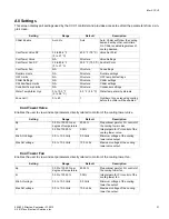
loop water flow and activates the chiller. An anti-cycle function provides configurable
Chiller settings
-->
Min On Time
and
Min Off Time
.
Chiller Setpoint Adjustment
The CCU1 provides setpoint adjustment control of the chiller by integrating to the factory mounted chiller controls with
a 0-10 VDC setpoint control signal. The chiller setpoint adjustment provides the ability for the user to change the chilled
water supply setpoint through the LCI. The analog output has a user adjustable scaling range.
Chiller Pump Control
The CCU1 includes support for two chilled water pumps, with only one pump required for normal operation. One of the
pumps is designated the lead pump, with the lag pump only being required in the event of a lead pump alarm. Each
time the chiller is deactivated, the lead pump designation is transferred to the other pump.
When the system is activated, the lead chiller pump is started. If the chiller pump has been commanded on for at least
20 seconds and the chiller flow is off, an alarm is initiated and the lag pump is started. The lag pump also triggers an
alarm if it has been commanded on for 20 seconds and flow proof is not established. If both chiller pumps fail, all out-
puts are turned off, all control stops, and a dual pump failure alarm is generated. Manual reset of the CCU1 controller
from the operator interface or by cycling power to the CCU1 is required to restart control.
Condenser Pump Control
The CCU1 also includes support for two condenser water pumps, with only one pump required for normal operation.
One of the pumps is designated to be the lead pump, with the lag pump only being required in the event of a lead pump
failure. Each time the chiller is deactivated, the lead pump designation is transferred to the other pump.
When the chilled water pump is started, the lead condenser pump is started also. If the condenser pump has been
commanded on for at least 20 seconds and the condenser flow is off, an alarm is initiated and the lag pump is started.
The lag pump also triggers an alarm if it has been commanded on for 20 seconds and flow proof is not established. If
both condenser pumps fail, all outputs are turned off, all control stops, and a dual pump failure alarm is generated.
Manual reset of the CCU1 controller from the operator interface or by cycling power to the CCU1 is required to restart
control.
Cooling Tower Bypass Valve Control
The cooling tower bypass valve is controlled when the CCU1 is configured for a water cooled chiller. The bypass valve
position is calculated by a Propor Integral (P+I) control loop based on the condenser water return temperature
and the condenser water setpoint. The bypass valve control loop is activated 15 seconds after the condenser water
flow proof has confirmed flow.
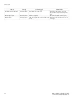
As the temperature increases above the
All Settings -> Cool Tower Valve SP
, the bypass valve is modulated open. The
bypass valve is modulated closed as the water temperature decreases below the
All Settings -> Cool Tower Valve SP
.
The cooling tower bypass valve control loop is selectable for direct or reverse acting operation.

