background image

iWorX CCU1

505-022, Effective: September 23, 2010


19


© 2010 Taco Electronic Solutions, Inc.

Automatic Configuration

The CCU1 and iWorX Local Control Interface (LCI) use a self-configuring network management scheme requiring no 
external tools, binding, or L

ON

W

ORKS

 knowledge.  The LCI recognizes and configures the CCU1 when the controller’s 

service pin is pressed. The controller’s status light flashes green until the controller is configured, and will be solid 
green after the controller is configured.  Once the service pin has been pressed, no further action is required by the 
user; the controller is fully accessible to the LCI. Users may bind to SNVTs on the CCU1 with LNS or other L

ON

W

ORKS

tools if they wish.

The LCI also provides network supervision of the CCU1.  The LCI periodically sends a "ping" message to the CCU1, 
which elicits a response. If the response fails, an alarm is displayed on the LCI. The LCI also uses the "ping" message 
to refresh the occupancy mode and other system wide data.

Networking Controllers

Associations can only be done in a network with an LCI2 present. Please refer to the 

iWorX LCI2 Application Manual

for detailed instructions.

CCU1 can be associated and communicate with other controllers. CCU1 can receive the cooling demands form asso-
ciated control.

Following is a list of the controllers that can be associated with the CCU1.

• DXU  series
• HPU  series
• FCU series


To associate a CCU1 to controllers, start from the LCI main screen; press 

Controllers

 and then select the CCU1. From 

within the CCU1, select 

HVAC Setup

 and then press the 

Members

 button. Once the members screen appears, a list of 

controllers that the CCU1 can be grouped to will be shown. Press the name of the controller to associate. The selected 
controller will turn “RED” color and “Associated” status will be displayed on the right side. To change the member status 
of a controller, just press that controller. It will toggle “Member” or “Non-Member” with each press. If a controller has 
been selected or deselected, you must press 

Save

 afterward to confirm the new setting. 

Summary of Contents for CCU1

Page 1: ...wer Source 6 Installation 6 Mounting the Device 6 Routing Cabling to the Device 7 Grounding the Device 7 Wiring Information 8 Connecting Input Devices 10 Connecting Output Devices 11 Other Connections 11 Specifications 12 Electrical 12 Mechanical 13 Application Description 14 Sequence of Operation 16 Chiller Activation 16 Chiller Setpoint Adjustment 16 Chiller Pump Control 16 Condenser Pump Contro...

Page 2: ...iWorX CCU1 2 505 022 Effective September 23 2010 2010 Taco Electronic Solutions Inc THIS PAGE LEFT BLANK INTENTIONALLY ...

Page 3: ...ponse to demand from other controllers Features Adjustable chiller setpoint Modulated cooling tower bypass valve Modulated cooling tower fan Minimum cycle timers for chiller On and Off Runtime accumulation for chiller pumps and fan Lead Lag operation of water pumps Maximum of 60 cooling zones Proportional Integral P I control of the modulated bypass valve Proportional Integral P I control of a var...

Page 4: ...Application Guide Document No 505 022 this docu ment Application Engineers Wholesalers Contractors Start up Technicians End user Provides instructions for setting up and using the iWorX CCU1 Controller iWorX LCI2 Application Guide Doc ument No 505 002 Application Engineers Installers Service Personnel Start up Technicians End user Provides instructions for setting up and using the iWorX Local Cont...

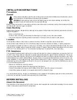
Page 5: ...trol enclosure Operate where ambient temperatures do not exceed 140 F 60 C or fall below 32 F 0 C and relative humidity does not exceed 90 non condensing FCC Compliance This equipment has been tested and found to comply with the limits for a Class A digital device pursuant to Part 15 of the FCC rules These limits are designed to provide reasonable protection against harmful interference This equip...

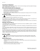
Page 6: ...xternal power source not supplied to operate The controller power input requires a voltage of 24 Volts AC To calculate power source current requirements add the power consumption of all peripheral devices to that of the controller The controller and triac output loads can use the same power source If both are using the same power source the loads must have EMF protection This protection can be int...

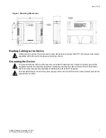
Page 7: ...the control enclosure and wiring conduit Grounding the Device The ground terminal T40 must be securely connected to earth ground Failure to properly ground this equipment will result in improper operation Improper grounding may also increase the risk of electrical shock and may increase the possibility of interference with radio TV reception For best performance connect the power supply common ter...

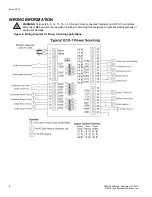
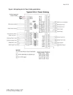
Page 8: ...IRING INFORMATION WARNING Terminals 6 9 12 15 18 33 36 and 38 are connected internally on all CCU1 controllers Disconnect ALL power sources when installing or servicing this equipment to prevent electrical shock or equipment damage Figure 2 Wiring Diagram for Power Sourcing applications ...

Page 9: ...iWorX CCU1 505 022 Effective September 23 2010 9 2010 Taco Electronic Solutions Inc Figure 3 Wiring Diagram for Power Sinking applications ...

Page 10: ...hiller water return thermistor to the unit attach one wire from the thermistor to CWR T17 and the other wire to the adjacent common T18 The thermistor used must be a 10K Precon Type III Condenser Supply Temperature CDS To connect the condenser water supply thermistor to the unit attach one wire from the thermistor to CDS T16 and the other wire to the adjacent common T15 The thermistor used must be...

Page 11: ...to CHP1 T31 and TC12 T30 and connect pump 2 to CHP2 T29 and TC12 T30 Condenser Pumps 1 2 CDP1 CDP2 The outputs for the pumps must be connected to 24 VAC pilot relays if the load is greater than 1 Amp for each pump If the load is less than 1 Amp connect pump 1 to CDP1 T28 and TC34 T27 and connect pump 2 to CDP2 T26 and TC34 T27 Chiller Low Limit CLL The output for the chiller low limit interface mu...

Page 12: ...Max Outputs Chiller Pumps 1 2 Condenser Pumps 1 2 Chiller Low Limit 24 Volts AC 1A 50C 0 5A 60C limited by the Class 2 supply rating Chiller Setpoint Cooling Tower Valve Cooling Tower Fan 0 10 Volts DC 2K Ohm minimum load 8 bit resolution Recommended Sensor Wire FTT 10A Network Speed 78KBPS Cabling Maximum node to node distance 1312 feet 400 meters Maximum total distance 1640 feet 500 meters For d...

Page 13: ... 0 32 kilograms Shipping Weight 1 0 pounds 0 46 kilograms Electronics Processor 3150 Neuron 10 MHz Flash 48 Kilobytes SRAM 8 Kilobytes Termination 0 197 5 0 mm Pluggable Terminal Blocks 14 22 AWG Environmental Temperature 32 F to 140 F 0 C to 60 C Humidity 0 to 90 non condensing Agency Listings UL Listed for US and Canada Energy Management Equipment PAZX and PAZX7 Agency Compliances FCC Part 15 Cl...

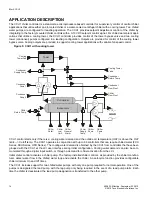
Page 14: ...ondenser Supply Temp Chiller Pump 1 Chiller Pump 2 Chiller Setpt Chiller Low Limit Cooling Tower Valve Cooling Tower Fan Condenser Pump 1 Condenser Pump 2 with cooling tower CCU1 control starts only if there is a cooling water demand and the outside air temperature OAT is above the OAT limits Cutoff temp The CCU1 operates in conjunction with up to 60 controllers that can require chilled water FCU ...

Page 15: ...r setpoint The bypass valve control loop is activated 15 seconds after the condenser water flow proof has confirmed flow As the temperature increases above the condenser water setpoint the bypass valve is modulated open The bypass valve is modulated closed as the water temperature decreases below the condenser setpoint The cooling tower bypass valve control loop is selectable for direct or reverse...

Page 16: ... other pump When the system is activated the lead chiller pump is started If the chiller pump has been commanded on for at least 20 seconds and the chiller flow is off an alarm is initiated and the lag pump is started The lag pump also triggers an alarm if it has been commanded on for 20 seconds and flow proof is not established If both chiller pumps fail all out puts are turned off all control st...

Page 17: ...er setpoint the fan speed is increased The fan speed is decreased as the water temperature decreases below the Chiller settings setpoint The fan speed control loop is selectable for direct or reverse acting operation To prevent the integral component from becoming too large there is anti wind up reset protection This protection clamps the integral value when all of the components add up to more th...

Page 18: ...rm is sent to the LCI Water Temperature Alarms After a 1 minute delay following chiller startup the CCU1 generates high and low limit alarms for the monitored water temperatures A programmable water temperature alarm limit offset is provided The temperature limits are calculated based on the alarm limit setpoints and the alarm limit offset Chiller Temp High Limit Chiller Settings Max Water Temp Wa...

Page 19: ...ssage to refresh the occupancy mode and other system wide data Networking Controllers Associations can only be done in a network with an LCI2 present Please refer to the iWorX LCI2 Application Manual for detailed instructions CCU1 can be associated and communicate with other controllers CCU1 can receive the cooling demands form asso ciated control Following is a list of the controllers that can be...

Page 20: ...f On Status of the CDFP switch Chlr General Alarm Off On Status of the chiller s alarm output Cooling Water Demand Off On Status of the CWD switch Chiller Supply Temp 30 00 to 230 00 F 34 40 to 110 00 C Temp reported by CWS sensor Chiller Return Temp 30 00 to 230 00 F 34 40 to 110 00 C Temp reported by CWR sensor Condenser Supply Temp 30 00 to 230 00 F 34 40 to 110 00 C Temp reported by CDS sensor...

Page 21: ...settings Chiller Settings NA Structure Chiller settings Chlr Alm Temp Limits NA Structure Chiller settings Cond Alm Temp Limits NA Structure Condenser settings Water Temp Alarm Hys 0 to 10 0 F 0 to 5 6 C 5 0 F 2 8 C Water temp alarm hysteresis Zone Limit 0 to 60 1 Number of zones requiring cooling before the chiller will be enabled Setting Range Default Description Kp 0 00 to 100 00 per degree of ...

Page 22: ...hich low limit control is enabled Cutoff Temp 32 00 to 140 00 F 0 00 to 60 00 C 52 0 F 11 1 C Outdoor air temperature below which the chiller is disabled Setting Range Default Description Setpoint 32 00 to 80 60 F 0 to 27 00 C 44 9 F 7 2 C Desired temperature of the chiller supply Type Water Air Water Type of chiller being controlled water cooled or air cooled Min Supply Temp 32 00 to 80 60 F 0 00...

Page 23: ...eater than Chiller Return Temperature Max plus water temperature limits Automatic when chiller return temper ature returns to normal range Chil Ret Low Temp Alarm Normal Alarm If Chiller water return temperature is less than Chiller Return Temperature Min minus water temperature limits Automatic when chiller return temper ature returns to normal range Cond Sup High Temp Alarm Normal Alarm If Conde...

Page 24: ...ser pump 2 fails Automatic unless there is a Dual Pump Failure See Dual Pump Fail ure Dual Pump Failure Normal Alarm If both pumps fail Reset the controller power cycle Chiller Alarm Normal Alarm This is a physical input received from the chiller Automatic when chiller returns to nor mal range Alarm Range Alarm Trigger Alarm Reset ...

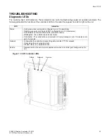
Page 25: ...ion Status Solid green when running and configured by an LCI networking Flashing green when running and NOT configured by an LCI stand alone Solid red when a fault condition exists control shut down Blinking Red the controller has a device failure Solid Amber The controller has not received a LCI ping message in over 10 minutes and is part of a network Network Yellow while the controller is transm...

Page 26: ...puts are dry contacts and that no voltage is being applied or switched to the inputs How do I associate my other control lers with the CCU1 Use the CCU1 s grouping mechanism specifically HVAC Setup Members on the CCU1 screen of the LCI What iWorX controllers can be part of a CCU1 s group Only FCU series DXU series and HPU series controllers can be part of the CCU1 s group and demand cooling from i...

Page 27: ...ranty TES products are not intended for use to sup port fire suppression systems life support sys tems critical care applications commercial aviation nuclear facilities or any other applica tions where product failure could lead to injury to person loss of life or catastrophic property damage and should not be sold for such pur poses If in doubt as to whether a particular product is suitable for u...

Reviews: