background image


Pinner_UM_9752092710_NL_D_GB_F_V2_0                                                                                                                                            15 


GB 

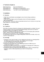
4. Technical specifications 

 
Operating voltage: 

30 kV DC


max. 

Operating distance: 

12.5


mm minimum at 30 kV

.


Short-circuit current: 

375 µA


at 30 kV (HV


resistance 80 M

). 

Operating temperature: 

200°C


max. (at the top of the electrode). 


5. Installation 


5.1. Checks 


Check that the electrode is undamaged and that you have received the correct version. 

- Check that the data on the packing slip corresponds with the data shown on the product 
   received. 

If you have any problems andlor in the case of ambiguity.


please contact Simco-Ion or your regional agent.


5.2. Installation 


5.2.1. Summary 

 
The distance from the electrode to the material should be established by experiment.  When 
adjusted properly, there should be sufficient bonding of the material and no spark-over from the 
points must occur. 
Metal parts in the immediate vicinity of the electrode cause a shift in the electric field.  As a 
result, the charging effect is disrupted. The minimum distance between electrode and metal 
parts must be 75 mm. 

If you have any questions concerning the installation: 
please contact Simco-Ion or your regional agent.


5.2.2. Installation 

 
1. Using the screws supplied, fit the 2 clips to the mounting strip. 
    Minimum distance between the clips 50 mm. 
2. Clamp the electrode in the clips 
3. Mount the unit in the place where charging is required (keeping it at a distance of 
    approx. 12.5 mm from the material to be charged). 
4. Using the assembly clamps supplied, fix the HV cable alongside the machine frame to the 
    DC high voltage power unit. 
5. Using the spring connector, connect the HV cable to the DC high voltage power unit (please 
    refer to the manual of the DC high voltage power unit).  
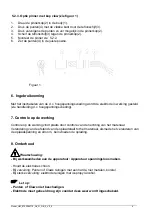
    See 5.2.3 for information on how to fit the pinner claw. 


Warning: 

-


Do not lay high voltage cables along sharp metal parts or in sharp bends and do not 

kink them. 

-


Keep high-voltage cables separated from low-voltage wiring. 

-   Metal parts near the electrode, including the machine frame, must be earthed.

Summary of Contents for Simco-Ion Pinner

Page 1: ...des chargeants SIMCO Nederland B V Postbus 71 NL 7240 AB Lochem Telefoon 31 0 573 288333 Telefax 31 0 573 257319 E mail general simco ion nl Internet http www simco ion nl Traderegister Apeldoorn No 0...

Page 2: ...nstallatie 3 5 1 Controle 3 5 2 Montage 3 5 2 1 Overzicht 3 5 2 2 Montage algemeen 3 5 2 3 Optie pinner met kop claw zie figuur 1 4 6 Ingebruikneming 4 7 Controle op de werking 4 8 Onderhoud 4 9 Stori...

Page 3: ...nt te geschieden door een elektrotechnisch vakbekwaam persoon Raak geen onder spanning staande punten aan Hierdoor krijgt u een onaangename elektrische schok Metalen delen in de omgeving van de Pinner...

Page 4: ...chuiving van het elektrisch veld waardoor het oplaadeffect wordt verstoord De afstand van de elektrode tot metalen delen moet minimaal 75 mm bedragen Bij vragen over montage Neem contact op met Simco...

Page 5: ...gesteld zie handleiding d c hoogspanningsvoeding 7 Controle op de werking Controle op de werking vindt plaats door controle van de hechting van het materiaal Verandering van de afstand van de oplaads...

Page 6: ...rode vervuilt Reinig de elektrode Vonkoverslag vanaf elektrode Hoogspanning te hoog ingesteld Verlaag de hoogspanning Afstand van elektrode tot materiaal te klein Monteer de elektrode verder van het m...

Page 7: ...oduct de lokaal geldende milieu regels 12 Reserve onderdelen Artikel nr Omschrijving 3927500110 Oplaadkop 5 Point 6927500205 Oplaadkop lineair 6 Point 6927500600 Oplaadkop Pinner Claw 3927900025 Body...

Page 8: ...n 9 5 1 Kontrolle 9 5 2 Montage 9 5 2 1 berblick 9 5 2 2 Montage 9 5 2 3 Option Pinner mit Kopfklaue siehe Abbildung 1 10 6 Inbetriebnahme 10 7 Funktionspr fung 10 8 Wartung 11 9 St rungen 11 10 Repar...

Page 9: ...lu und Reparaturarbeiten sind von elektrotechnisch fachkundigem Personal durchzuf hren Ber hren Sie keine spannungsf hrenden Spitzen Sie werden sonst einen unangenehmen Stromschlag empfinden In der N...

Page 10: ...on den Spitzen aus auftreten Metallteile in unmittelbarer Elektrodenn he verursachen eine Verschiebung des elektrischen Feldes Hierdurch wird die Aufladewirkung gest rt Die Elektrode mu mindestens 75...

Page 11: ...achen Seite durch die Teflonscheibe 3 9 Dr cken Sie anschlie end die Spitzen so weit wie m glich in den Pinnerkopf 2 10 Schieben Sie die Teflonscheibe 3 gegen den Pinnerkopf 2 11 Montieren Sie den Pin...

Page 12: ...hspannungs Netzteil einschalten Defektes Hochspannungs Netzteil Hochspannungs Netzteil ausbessern Defekter Hochspan nungswiderstand in Elektrode Hochspannungswiderstand auswechseln Unterbrechung in de...

Page 13: ...HS Verkabelung auswechseln 1 Aufladekopf abschrauben 2 Widerstand herausnehmen 3 Stellschraube der Zugentlastung der HS Verkabelung l sen 4 Verkabelung weiterschieben 5 Federkontakt ausbauen 6 HS Ver...

Page 14: ...15 5 1 Checks 15 5 2 Installation 15 5 2 1 Summary 15 5 2 2 Installation 15 5 2 3 Pinner with head claw option see Figure 1 16 6 Putting into use 16 7 Functional check 16 8 Maintenance 16 9 Faults 17...

Page 15: ...ctrical installation and repairs shall be made by a skilled electrical engineer Do nor touch any live points You will get an unpleasant electrical shock Metal parts near the Pinner electrode including...

Page 16: ...he electric field As a result the charging effect is disrupted The minimum distance between electrode and metal parts must be 75 mm If you have any questions concerning the installation please contact...

Page 17: ...h voltage power unit please refer to the manual of the DC high voltage power unit 7 Functional check The proper functioning is established by checking the material bonding Charging is affected by chan...

Page 18: ...Clean the electrode Spark over from electrode High voltage set too high Reduce high voltage Distance from electrode to material too small Mount the electrode farther away from the material Table 1 fa...

Page 19: ...mental and other rules when disposing of the product 12 Spare parts Item No Description 3927500110 5 point charging head 6927500205 Linear 6 point charging head 6927500600 Pinner claw head 3927900025...

Page 20: ...tr le 21 5 2 Montage 21 5 2 1 Aper u 21 5 2 2 Montage 21 5 2 3 Option lectrode avec t te griffe voir figure 1 22 6 Mise en service 22 7 Contr le du fonctionnement 22 8 Entretien 22 9 Pannes 23 10 R pa...

Page 21: ...e r alis es par un lectricien qualifi Ne pas toucher des l ments sous tension Vous risqueriez de recevoir une d charge lectrique Les parties m talliques aux abords de l lectrode Pinner doivent tre mis...

Page 22: ...n de l effet de chargement La distance entre l lectrode et les parties m talliques doit tre d au moins 75 mm Pour plus d informations ce sujet Contactez Simco Ion ou son agent dans votre r gion 5 2 2...

Page 23: ...atique DC sous tension voir la notice d utilisation du g n rateur d lectricit statique DC 7 Contr le du fonctionnement Le contr le du fonctionnement consiste contr ler l adh sion du mat riau Le charge...

Page 24: ...ter augmenter le courant de chargement La distance entre l lectrode et le mat riau est trop grande Monter l lectrode plus pr s du mat riau lectrode encrass e Nettoyez l lectrode D charge partir de l l...

Page 25: ...ressort 6 Remplacez le c ble HT 7 Montez l ensemble dans l ordre inverse 11 Mise au rebut Observez les lois nationales en vigueur en cas de mise au rebut de l appareil 12 Pi ces de rechange R f rence...

Reviews: