ROVINS – User Manual
MU–ROVINS–AN–013 Ed. A – March 2012
20
V.2 Listing of Interfaces
ROVINS is fitted with 5 connectors configured to provide the following:
•
Power supply for ROVINS through the Port A&B or Ethernet connector
•
2 independent power lines for external sensor allowing to power sensors with different
voltages: for example, a DVL powered in 24V and a SVP sensor powered with 12V
•
1 Repeater and configuration port either through the Ethernet connector (in RS232
only) or through the Port A&B one (in both RS232 and 422),
•
5 Inputs/ Outputs RS232/422 or Ethernet user-configurable
•
3 user-configurable pulse Inputs A, B and C
•
2 user configurable pulse Outputs A and B
•
1 external pulse (coming from the surface through the central connector and then
dispatched to all other connectors): it can be used to output a trigger for the DVL (i.e.,
to allow the DVL to ping at chosen time)
V.3 Port A&B Connector (Central Connector) Specifications
The central connector is used when Ethernet is not available, to power and to connect
ROVINS to a PC for installation, configuration and display purposes through the Web-
based User Interface which is embedded in the unit. Refer to document
INS
-
Configuration & Operation with the Web-based User Interface (Ref.:
MU-INSIII-AN-002
)
for details on ROVINS configuration with this Web-based User Interface. In this
configuration, the Web server connection will need to be configured in PPP.
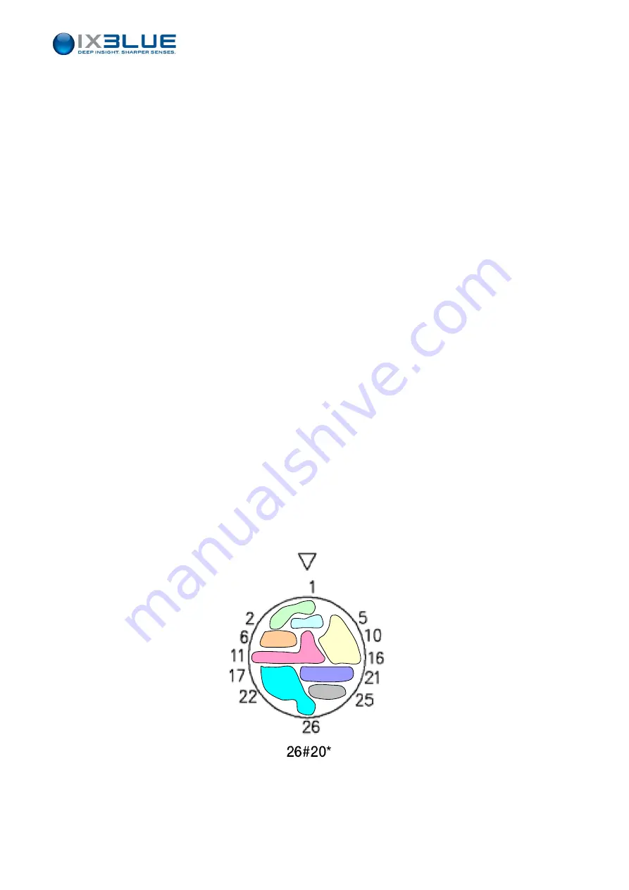
The ROVINS unit is powered by 24 Volts direct current. ROVINS central connector is
configured as shown in Figure 7.
Figure 7 - Central connector
The full pin assignment for the central connector is described in Table 1.
Summary of Contents for ROVINS
Page 1: ...ROVINS User Manual...
Page 2: ......
Page 6: ......
Page 14: ...ROVINS User Manual MU ROVINS AN 013 Ed A March 2012 8 PAGE INTENTIONALLY LEFT BLANK...
Page 16: ...ROVINS User Manual MU ROVINS AN 013 Ed A March 2012 10 PAGE INTENTIONALLY LEFT BLANK...
Page 18: ...ROVINS User Manual MU ROVINS AN 013 Ed A March 2012 12 PAGE INTENTIONALLY LEFT BLANK...
Page 20: ...ROVINS User Manual MU ROVINS AN 013 Ed A March 2012 14 PAGE INTENTIONALLY LEFT BLANK...
Page 22: ...ROVINS User Manual MU ROVINS AN 013 Ed A March 2012 16 Figure 4 Centering pin locations...
Page 24: ...ROVINS User Manual MU ROVINS AN 013 Ed A March 2012 18 PAGE INTENTIONALLY LEFT BLANK...


