background image


Page 38 


Summary of Contents for CHLORGUARD

Page 1: ...DOCUMENT No CHL07 M PART No CHL01 REVISION 3 1 6 20 12 2015 CHLORGUARD USER S MANUAL...

Page 2: ...given an appropriate level of training in chlorine safety practices and know the location of safety equipment Orica has wall charts and handbooks available which describe safe practice in storing and...

Page 3: ...e Logic Controller 15 3 1 4 DC UPS power supply 15 3 1 5 Chlorine Sensor Transmitter 15 3 1 6 Closing Actuators 16 3 1 6 1 Electric Actuators 16 3 1 6 2 Pneumatic Actuators 16 3 1 6 3 Air Regulator 16...

Page 4: ...ator 26 4 1 16 Electric Actuator Fitted to International Yoke Acromet Prominent Vacuum Regulator 27 4 1 17 Pneumatic Actuator and Support Bracket Assembly 28 4 1 18 Pneumatic Actuator Fitted to Chlori...

Page 5: ...n system for chlorine cylinders and drums Operation of the system is initiated by an integral PLC and a Chlorine Sensor Transmitter local to the chlorine container Further means of initiation can be b...

Page 6: ...Page 6 1 2 Typical Setup 920Kg Drums...

Page 7: ...s A Control panel B Actuator Electric or Pneumatic C Cl2 sensor D Frame support of control panel E Air Systems only if the systems is pneumatic F Support bracket G Connecting Transmitting Key The foll...

Page 8: ...Up to 8 Actuators electrical or pneumatic Pneumatic solenoid valve input and output External devices SCADA Alarms etc The Control Panel internal distribution design differs in the cabinet regarding if...

Page 9: ...Page 9 Control Panel Electric Front View Control Panel Pneumatic Front View...

Page 10: ...power supply c PLC Programable Logic Controller d GMS wireless module e Battery f Relays Auxiliary relay base of the relay and auxiliary relay g Warning LED s Visual Alarm 3 Flashing light h Connector...

Page 11: ...the status and alarm conditions of the ChlorGuard system for up to 4 operator phone contacts if required Important information such as chlorine releases and alarms are immediately transferred by wire...

Page 12: ...The patented support bracket has capability of attachment to both the pneumatic or electric type actuators and is made from mild steel and powder coated Electric Support Bracket Pneumatic Support Brac...

Page 13: ...meets the following requirements Functional Safety acc To IEC 61508 IEC 61511 1 Explosion protection acc to EN 50014 and EN 50020 Electromagnetic Compatibility EMC acc To EN 50270 The Sensor consists...

Page 14: ...Page 14 DRAGER SENSOR DRAGER TRANSMITTER...

Page 15: ...C UPS power supply The DC Uninterrupted Power Supply UPS provides reliable 24 VDC Power Supply load to the ChlorGuard system If there is AC input it will provide power supply for the load and at the s...

Page 16: ...signal a timer has been set to stop the electric actuator after a set time that assures the valve is closed 3 1 6 2 Pneumatic Actuators These inputs activate the PLC and associated relays to activate...

Page 17: ...PLC manages the operating function for the ChlorGuard 7 system Each ChlorGuard 7 system PLC is programmed prior using standard logic Once the PLC is programmed and set there is no further need to adj...

Page 18: ...diately transferred by wireless to operators letting them know when and how much chlorine is in the work area Operators can use their phones to log into the ChlorGuard system to check the status of th...

Page 19: ...NT SCADA OUTPUT PIN NUMBER CONTACT RESPONSE Total loss of power AC and low battery charge PLC failure Sensor Failure Drager Polytron 7000 Low air Pressure pneumatic model System Healthy 1 Open in the...

Page 20: ...Page 20 SCADA DIGITAL OUTPUT DIAGRAM Socket Circuit Diagram at Chlorguard panel bottom...

Page 21: ...e input connection will trip the Shutdown sequence when is activated This input could be connected to external devices like a Mushroom Style Button or SCADA platform SCADA DIGITAL INPUT DIAGRAM Emerge...

Page 22: ...operating system 4 1 9 Chlorine Sensor Pin Inputs There are two chlorine sensor inputs analogue which can be used to activate the ChlorGuard system to close the chlorine container valves 4 1 10 Elect...

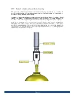
Page 23: ...port bracket and interconnecting key assembly is used to close the chlorine container valves The electric actuator is set for a specified torque of 30Nm which is sufficient to tightly close the contai...

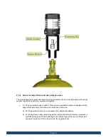
Page 24: ...Institute yoke is used to fit the vacuum regulators Siemens equipment the support bracket simply fits between the valve body and yoke a For 70kg cylinders there is no requirement for additional adapto...

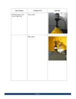
Page 25: ...Page 25 Type of Fitting Container Size Assembly Standard Fitting with No Vacuum Regulators 70kg Cylinder 920kg Drums...

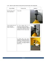
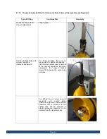
Page 26: ...uipment For 70kg cylinders there is no requirement for additional adaptors If a Chlorine Institute yoke is used to fit the vacuum regulators Siemens equipment the support bracket simply fits between t...

Page 27: ...nt equipment For 70kg cylinders a small 20mm spacer will be required to be used between the yoke clamp and valve body to allow an easy fit of the support bracket and interconnecting key If an Internat...

Page 28: ...o the spindle on the valve A slight alignment of the interlocking key to the spindle can be done by simply turning the actuator manually with your fingers or open end spanner To fix the support bracke...

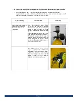
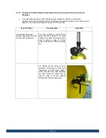
Page 29: ...equipment For 70kg cylinders there is no requirement for additional adaptors If a Chlorine Institute yoke is used to fit the vacuum regulators Siemens equipment the support bracket simply fits betwee...

Page 30: ...of the bracket Type of Fitting Container Size Assembly International Yoke with vacuum regulators Acromet Prominent equipment For 70kg cylinders a small 20mm spacer will be required to be used between...

Page 31: ...he Touch Screen Chlorguard Main Screen Figure 1 Control Description System Function 1 Alarm Configuration Function 2 SMS Configuration Function 3 Leak Detection Simulation Test Function 4 Service Menu...

Page 32: ...t alarm activities By pressing the touch screen in the alarms field you ll open the Alarm Log see fig 3 Alarm Log Displays the date time and description of all alarm activities The Arrow keys allow yo...

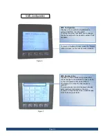
Page 33: ...5 you must press the touch screen in the Password field To return to the Main Screen press the Return to Main Screen on the touch screen interface SMS Configuration Password Entry Displays a Password...

Page 34: ...o return to the Main Screen press the Return to Main Screen on the touch screen interface SMS Number Entry Displays a phone number entry screen that allows change to the selected number see fig 6 the...

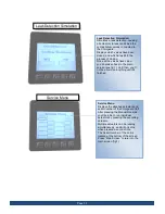
Page 35: ...taken back to the main screen see fig 1 Until then you ll not be able to do anything until it s finished Service Menu Displays the attached actuators and serial number of the Chlorguard Unit After pre...

Page 36: ...Page 36...

Page 37: ...Page 37 5 APPENDICES ChlorGuard Assembly Diagram Figure 6 Control Module Functional Block Diagram W0500389 Electrical Schematic W0500456...

Page 38: ...Page 38...
Reviews: