Page 4
4.1.13
Electric Actuator and Support Bracket Assembly .................................................. 23
4.1.14
Electric Actuator Fitted to Standard Chlorine Valve ............................................... 24
4.1.15
Electric Actuator Fitted to Chlorine Institute Yoke & Siemens Vacuum Regulator . 26
4.1.16
Electric Actuator Fitted to International Yoke & Acromet/Prominent Vacuum
Regulator ............................................................................................................................ 27
4.1.17
Pneumatic Actuator and Support Bracket Assembly ............................................. 28
4.1.18
Pneumatic Actuator Fitted to Chlorine Institute Yoke and Siemens Vacuum
Regulator ............................................................................................................................ 29
4.1.19
Pneumatic Actuator Fitted to International Yoke and Acromet/Prominent Vacuum
Regulator ............................................................................................................................ 30
4.1.20
PLC Touch Screen Operation Menus.................................................................... 31
5
Appendices ............................................................................. 37
Summary of Contents for CHLORGUARD
Page 1: ...DOCUMENT No CHL07 M PART No CHL01 REVISION 3 1 6 20 12 2015 CHLORGUARD USER S MANUAL...
Page 6: ...Page 6 1 2 Typical Setup 920Kg Drums...
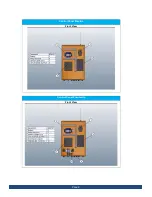
Page 9: ...Page 9 Control Panel Electric Front View Control Panel Pneumatic Front View...
Page 14: ...Page 14 DRAGER SENSOR DRAGER TRANSMITTER...
Page 20: ...Page 20 SCADA DIGITAL OUTPUT DIAGRAM Socket Circuit Diagram at Chlorguard panel bottom...
Page 36: ...Page 36...
Page 38: ...Page 38...


