background image

Ixom employs qualified highly trained Service and Placement Technicians certified to perform the 

necessary tasks required to install or remove SolarBee and GridBee circulation equipment

Ixom's specialized Service and Placement Technicians are trained in Confined Space, Fall Protection, 

and other related subjects as required by OSHA to perform the necessary work to install or remove 

SolarBee and GridBee equipment, and are knowlegeable in the regulations and standards of OSHA.

If you feel the need to service your SolarBee or GridBee circulation equipment, please contact Ixom's 

Customer Service Department at:

+1 866 437 8076

Ixom Service & Support

© 2020 Ixom | www.medoraco.com | 866 - 437 - 8076 | info@medoraco.com

Service & Support

1928_10001_20200420

O&M_SN1_10055_20200529 - 22

Summary of Contents for Medora GridBee SN 1

Page 1: ... 2020 Ixom www medoraco com 866 437 8076 info medoraco com O M_SN1_10055_20200529 GridBee SN 1 Owner s Manual ...

Page 2: ...r Wastewater Treatment Processes Ixom equipment continues to be at the forefront as the 1 world leader for in situ water body treatment 2020 Ixom www medoraco com 866 437 8076 info medoraco com Table of Contents 10014_20200528 GridBee SN 1 Owner s Manual Safety 1 Package Contents 4 Requirements 6 Electrical 7 Assembly 8 Final Checklist 14 Operation 15 Technical Specifications 16 Exploded Parts Dia...

Page 3: ...ipment You can avoid hazards by following these safety instructions and applying some ordinary common sense when operating or servicing this unit Keep in mind that full operator attention and alertness are required when operating or servicing this unit USE COMMON SENSE Most accidents can be avoided by using common sense and concentration on the job being done 2020 Ixom www medoraco com 866 437 807...

Page 4: ...sentative ELECTRICAL HAZARD WARNING THIS EQUIPMENT CONTAINS HIGH VOLTAGE ELECTRICAL SHOCK CAN CAUSE SERIOUS OR FATAL INJURY ONLY QUALIFIED PERSONNEL SHOULD ATTEMPT PLACEMENT OPERATION AND MAINTENANCE OF ELECTRICAL EQUIPMENT REMOVE ALL SOURCES OF ELECTRICAL POWER BEFORE PERFORMING ANY SERVICE WORK TO THE MACHINE USE PROPER LOCKOUT TAGOUT LOTO PROCEDURES TO ENSURE A SAFE WORK ENVIRONMENT Rotating Ha...

Page 5: ...omply with all relative OSHA and local regulations while installing and performing any maintenance to the mixer circulation equipment Key OSHA Compliance Standards that must be followed and not limited to are 1910 146 Permit required confined spaces 1910 147 Lockout Tagout 1926 500 Fall Protection Fall Protection Tips Identify all potential tripping and fall hazards before work starts Look for fal...

Page 6: ...Submersible Electric Cord Crate Unpacking Note A 2 Square Driver Bit is required for crate disassembly 50 Stainless Steel Retrieval Chain Hardware Kit SN1 White Tote Kit F1 Ventilation Blower Completely Assembled 2020 Ixom www medoraco com 866 437 8076 info medoraco com Package Contents 10062_20200221 O M_SN1_10055_20200529 4 ...

Page 7: ...nt Tube 2 Kellem Grip Cord Strain Reliefs Universal Fixture 3 Hair Pins 2 6 Hose Clamps 5 16 Nut Driver Not Supplied 3 Float Lock Clevis Pins Epoxy Tube Caulk Gun Not Supplied 6 Hose Tube Insert Epoxy Splice Kit Cord Grip 6 Quick Link 2020 Ixom www medoraco com 866 437 8076 info medoraco com Package Contents 10062_20200221 O M_SN1_10055_20200529 5 ...

Page 8: ... 1 Ground Terminate conduit using flex conduit with male thread end for panel mount Terminate conduit ends using flex conduit with SN1 Male 3 4 NPT LB or Disconnect Box F1 Ventilation Blower Male 1 2 NPT with nut 240vAC 30Amp Double Pole Circuit Breaker Locate power source flex conduit termination at customer preferred location of Mixer Control Panel TYPE RATING FULL LOAD MAXIMUM LOAD WINDING RES ...

Page 9: ...208VAC 60HZ 3 Phase Motor Resistance 11 5 Ω 0 8 Amps 460VAC 60HZ 3 Phase Motor Resistance 43 0 Ω Service Factor 1 15 L1 2 L2 L1 L2 8 1 3 2 8 5 3 4 1 5 4 INTERCHANGE 5 AND 8 LEADS TO REVERSE ROTATION LOW VOLTAGE LOW VOLTAGE HIGH VOLTAGE HIGH VOLTAGE 6 4 5 7 8 9 1 2 3 6 4 5 7 8 9 1 2 3 L2 L1 L3 L2 L1 L3 2020 Ixom www medoraco com 866 437 8076 info medoraco com Electrical Wiring for F1 Ventilation Bl...

Page 10: ...ir Penetration 1 Locate 2 1 2 Hole Saw 1 25 Bulkhead Fitting and Lexel Tube from Package Contents 2 Determine penetration point that is A within arms reach of the access hatch in the tank roof and B relatively close to directly above the SN1 Spray Unit position Do not install below tank overflow water level 3 Make sealed penetration referencing the following diagram Tools Required Cordless Drill L...

Page 11: ... Locate 6 Hose Tube Insert 6 Hose Clamp and Torque Bar Assembly from Package Contents 2 Slide 6 Hose Tube Insert inside the the lower end of the 6 Hose until it is flush with the end 3 Open the 6 Hose Clamp up by loosening screw slide it through either of the two slots on Torque Bar Assembly 4 Close the 6 Hose Clamp up by hand tightening screw 5 Slide the 6 Hose Clamp over the end of the hose so i...

Page 12: ...VC pipe full with epoxy 8 Bolt bracket to SN1 Core Unit using M8 bolt in Epoxy Splice Kit 9 Avoid tipping upside down for 60 minutes or until set then clamp PVC pipe to bracket with small hose clamp Tools Required Caulking Gun Wire Stripper Crimper Pliers and 13mm or 1 2 box end socket wrench 3 4 5 6 7 Submersible Electric Cord top side 1 Loosen interior cord grip on the Universal Fixture and slid...

Page 13: ...trieval Chain to Eyelet at the very top of the SN1 Core Unit by making a small loop and using Quick Link to secure the loop of chain 3 Run opposite end of Retrieval Chain through roof hatch and connect to the interior side of Universal Fixture using quick link 2 3 2020 Ixom www medoraco com 866 437 8076 info medoraco com Assembly 10077_20200221 O M_SN1_10055_20200529 11 ...

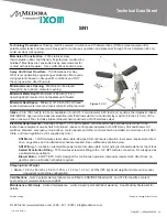
Page 14: ...eds to be expanded into it s cross configuration This involves A Removing an existing M8 bolt nut B Expanding Torque Bar then C Reinserting Tightening the M8 bolt nut 2 When the Collapsed SN1 Core Unit s Floats just pass all the way through the hatch they each need to be A expanded all the way out until the square tubing is set inside the float arm channel B Insert the Float Lock Pin and Hair Pin ...

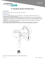
Page 15: ...Pipe so that the flange is facing the direction of the final F1 Ventilation Blower position determined 4 Position the F1 Ventilation Blower so that the flanges are close to aligning Make final alignment adjustments by moving the nuts on the two threaded rod feet 5 Insert the Flange Gasket in between the flanges then secure the flanges using the bolts nuts and washers 6 Finish by tightening the thr...

Page 16: ... properly sealed Assembly Are the top of tank electric splices correct and each splice individually sealed to protect from corrosion Assembly Is the field wiring correct Requirements Is The Mixer submerged in at least 4 1 2m of water Pre Operation Checks Reading Continuity Check Black to White Discontinuity Check White to Ground Black to Ground Source Voltage Reading Operation Check While Unit is ...

Page 17: ...d max load of the rated motor current The following table can be referenced for a SN1 Spray Unit HP Voltage Typical Full Load Amperage 1 5 230vAC 1 Phase 11 0 to 13 5 Amps Amperage Readings Below Full Load Amperage If amperage readings are signficantly below the Typical Full Load Amperage it may be indicating that there is an excessive restriction to the water flow of the machine or that the subme...

Page 18: ... designed as a submersible penetration SN1 Wiring 3 conductor submersible power cable for submersible motor wiring terminated exterior at top of tank SN1 Motor 1 5HP stainless steel submersible designed for continuous operation low power requirement direct drive no gearbox and no lubrication schedule required See certifications section below Materials of Construction T316 stainless steel thermopla...

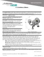
Page 19: ...lk head fitting T316 stainless steel tank fitting with a 2 1 2 diameter tank roof penetration required for air entry Penetration sealed with LEXEL rubber based sealant and rubber gasket to maintain integrity of the tank Not designed as a submersible penetration Wiring 3 conductors required for single phase motors 4 conductors required for three phase motors Electrical conduit body mounted to motor...

Page 20: ... 2020 Ixom www medoraco com 866 437 8076 info medoraco com Dimension Drawing F1 Ventilation Blower Dimension Drawing P N 100536 2000_10058_20200221 O M_SN1_10055_20200529 18 ...

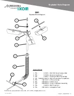
Page 21: ...ubmersible Pump Motor 5 PN 16013107 6 Hose Clamp 6 PN 26060640 6 NSF Hose 7 PN 26260640 Cross Torque Bar Assembly 8 PN 100459 SN1 Float Arm 9 PN 28010000 Collapsible Float 1 2 4 3 5 6 8 9 8 5 2020 Ixom www medoraco com 866 437 8076 info medoraco com Exploded Parts Diagram SN1 Exploded Parts Diagram 1975_10061_20200221 O M_SN1_10055_20200529 19 ...

Page 22: ...18 0 5m Minimum Head Space 48 1 2m Minimum Operating Depth 2020 Ixom www medoraco com 866 437 8076 info medoraco com Dimension Drawing SN1 Dimension Drawing 1958_10047_20200221 O M_SN1_10055_20200529 20 ...

Page 23: ...e parts There is no liability for consequential damages of any type The warranty that is submitted and provided with the purchased equipment is the valid warranty GridBee control panels and any optional accessories These items are considered buyout items for Ixom and as such include a warranty against defects in material and workmanship for one year from the date of purchase This warranty covers p...

Page 24: ...ion and other related subjects as required by OSHA to perform the necessary work to install or remove SolarBee and GridBee equipment and are knowlegeable in the regulations and standards of OSHA If you feel the need to service your SolarBee or GridBee circulation equipment please contact Ixom s Customer Service Department at 1 866 437 8076 Ixom Service Support 2020 Ixom www medoraco com 866 437 80...

Reviews: