background image

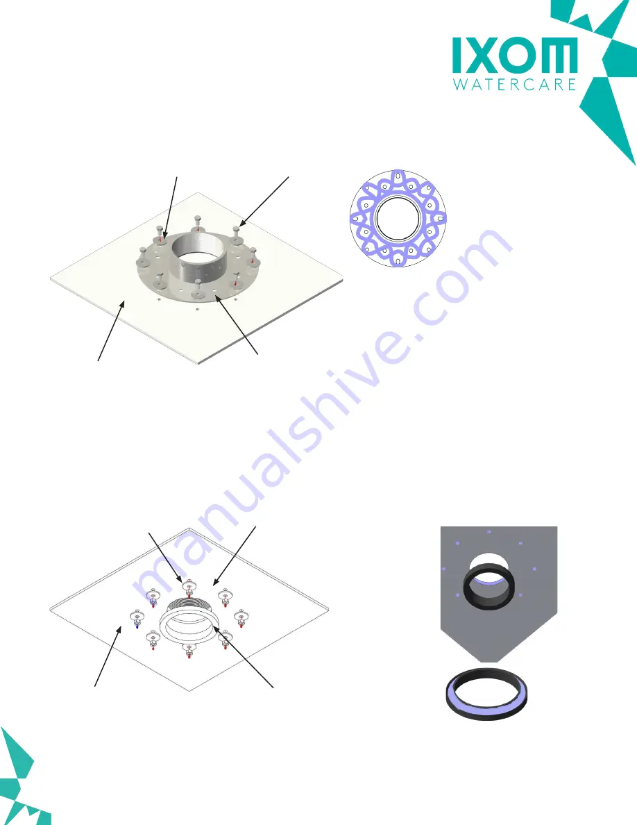
Figure 1: 

Outside Tank Bolt Installation

Figure 2: 

Inside Tank Bolt, Gasket and Flange Installation

Sheet Roof

Structure with Penetration 

Hole and Bolt Holes

4” Coupling Flange Assembly 

with Lexel Sealant 

(See Inset A for 

placement of Sealant)

Sheet Roof

Structure with Penetration 

Hole and Bolt Holes

Rubber Gasket 

with Lexel Sealant 

(See Inset B for 

placement of Sealant)

Fender Washer with

Lexel Sealant

M8 Nylock Nut

Fender Washer

M8 Bolt

Inset A

Inset B

*** 

NOT DESIGNED AS A

SUBMERSIBLE PENETRATION 

***

©2021 IXOM Watercare Inc. | www.ixomwatercare.com | 866 - 437 - 8076 | watercare@ixom.com

Integration

4" Coupling Flange Assembly

For Steel Roof Systems

1957_10046_20210428

O&M_SB2500PW_10248_20211110 - 22

Summary of Contents for SolarBee SB2500PW

Page 1: ...OM Watercare Inc www ixomwatercare com 866 437 8076 watercare ixom com 2021 IXOM Watercare Inc www ixomwatercare com 866 437 8076 watercare ixom com O M_SB2500PW_10248_20211110 SolarBee SB2500PW Owner s Manual ...

Page 2: ...210413 SolarBee SB2500PW Owner s Manual Safety 1 Operation 4 Site Preparation 5 Assembly 6 Features 24 Maintenance 26 Electrical 35 Troubleshooting 38 Parts Diagram 42 Dimension Drawing 43 Appendix 44 Technical Specifications 45 Warranty 59 Service Program 60 Customer Service 61 O M_SB2500PW_10248_20211110 ...

Page 3: ...u can avoid hazards by following these safety instructions and applying some ordinary common sense when operating or servicing this unit Keep in mind that full operator attention and alertness are required when operating or servicing this unit USE COMMON SENSE Most accidents can be avoided by using common sense and concentration on the job being done 2021 IXOM Watercare Inc www ixomwatercare com 8...

Page 4: ...ative ELECTRICAL HAZARD WARNING THIS EQUIPMENT CONTAINS HIGH VOLTAGE ELECTRICAL SHOCK CAN CAUSE SERIOUS OR FATAL INJURY ONLY QUALIFIED PERSONNEL SHOULD ATTEMPT PLACEMENT OPERATION AND MAINTENANCE OF ELECTRICAL EQUIPMENT REMOVE ALL SOURCES OF ELECTRICAL POWER BEFORE PERFORMING ANY SERVICE WORK TO THE MACHINE USE PROPER LOCKOUT TAGOUT LOTO PROCEDURES TO ENSURE A SAFE WORK ENVIRONMENT Rotating Hazard...

Page 5: ...h all relative OSHA and local regulations while installing and performing any maintenance to the mixer circulation equipment Key OSHA Compliance Standards that must be followed and not limited to are 1910 146 Permit required confined spaces 1910 147 Lockout Tagout 1926 500 Fall Protection Fall Protection Tips Identify all potential tripping and fall hazards before work starts Look for fall hazards...

Page 6: ...y which energizes the drive system s controls and motor Excess solar energy is stored during the day and used during the night allowing the SolarBee to operate during the night without being connected to the grid During operation a visible flow can be observed coming off the distributor dish and spreading outward The impeller of the SolarBee is designed to operate at full speed when there is suffi...

Page 7: ...follow at a later time once the reservoir is filled with water SANITARY REQUIREMENTS For potable water equipment installations it is very important to maintain sanitary conditions by properly disinfecting all equipment and personnel that come into contact with the reservoir interior and potable water It is recommended that once the hatch is chosen for equipment and personnell entry a clean zone be...

Page 8: ...e following pages give detailed instructions on how to assemble different portions of the machine however the order in which the components are assembled may need to be altered based on the hatch size and whether the reservoir will be dry or empty For instance the hose and intake assembly can be performed on the tank exterior prior to lowering the equipment inside if the hatch size is at least 6 f...

Page 9: ...ponent will fit through a hatch with clear unobstructed opening of at least 3 feet X 3 feet 0 92m X 0 92m STEP 5 Once these components are lowered through the hatch they can be reassembled using the opposite order of STEPS 1 4 Impeller Reinsertion STEP 1 Place impeller assembly back in place Slide lower coupling into upper coupling and allow to drop down into place Be sure bottom of impeller shaft...

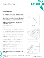
Page 10: ...up fitting it into the float arm Use the float pins to secure the float to the float arm STEP 5 Place hairpins in each float pin to secure it and prevent the pin from coming out STEP 6 Repeat Steps 1 through 5 for the other two floats NOTE The float plate may not be used on one of the three floats After familiarizing yourself with all the components and gathering the necessary tools you are ready ...

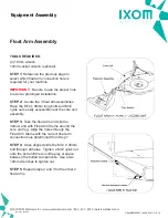
Page 11: ...TALLED SB10000 WITH 15FT 4 5m OR LESS HOSE SB10000 WITH 15FT 4 5m OR LESS HOSE SB 7500 20FT 4 5m OR LESS HOSE SB 7500 20FT 4 5m OR LESS HOSE ALL SB5000 ALL SB5000 ALL SB2500 ALL SB2500 ALL POTABLE WATER UNITS ALL POTABLE WATER UNITS ALL HIGH SALINITY SALTWATER APPLICATIONS ALL HIGH SALINITY SALTWATER APPLICATIONS Float Arm to Machine Attachment Assembly 2021 IXOM Watercare Inc www ixomwatercare co...

Page 12: ...ke the float arm and slip the narrow end with Float Arm Stems around the core unit leg Align the holes through the Float Arm Stems with the correct float arm connection hole determined from Step 1 STEP 4 Once aligned slide the M12 X 90mm bolt through all holes Tighten a M12 nylok nut onto the bolt until there is little play or space between the bolted components Use a two 19mm wrenches to tighten ...

Page 13: ...rnbuckle assembly is in place take the opposite end of the turnbuckle and slide it into the float arm assembly as shown in picture STEP 5 Align the hole through the shaft with the float arm assembly holes and slide the M12 90mm Bolt and tighten the Nylok nut STEP 6 Repeat steps 2 through 5 for each turnbuckle assembly IMPORTANT Hold the center of the turnbuckle assembly and turn both ends all the ...

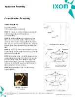
Page 14: ...3 Place one of the chain brackets over the square tubing with the wider side facing up and the opening facing outward STEP 4 Once the chain bracket is slid around the square tubing insert the M8 x 45mm bolt through the outer holes in the chain bracket Apply anti seize to the threads of the bolt Tighten the M8 nylok nut on the bolt to keep the chain bracket in place using two 13mm wrenches STEP 5 R...

Page 15: ...e leg extension to the machine Core unit assembly using a set of two 5 16 inch x 2 inch 8mm x 51mm clevis pins STEP 5 Secure both pins using two hair pins STEP 6 Repeat steps 2 through 5 for each leg extension NOTE Once the leg extensions are attached and secure the leg extensions act as a tri pod in which the machine can rest on Sliding Leg Extension Around Bottom Leg Of Core Unit Attaching Leg E...

Page 16: ...nut for each strainer leg STEP 3 Tighten all 4 bolts nuts using 13mm wrench and socket wrench STEP 4 Tilt or hoist the core unit assembly and slide the hose and intake plate assembly beneath the core unit assembly Line up the upper hose flange slots with the core machine unit flange slots STEP 5 Use M8x20 bolts and M8 nylok nuts to attach the upper hose flange to the core unit assembly flange STEP...

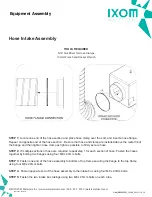
Page 17: ...ther by bolting two flanges using four M8 x 20mm bolts STEP 3 Fasten one end of the hose assembly to bottom of top frame securing the flange to the top frame using four M8 x 20mm bolts STEP 4 Fasten opposite end of the hose assembly to the intake box using four M8 x 20mm bolts STEP 5 Fasten the two intake box tubings using two M8 x 45mm bolts on each tube TOOLS REQUIRED 5 16 Nut Driver for Hose Cl...

Page 18: ...Injection Hose Assembly 2021 IXOM Watercare Inc www ixomwatercare com 866 437 8076 watercare ixom com Equipment Assembly 458_10264_20210921 O M_SB2500PW_10248_20211110 16 ...

Page 19: ...ress the two halves together STEP 4 Install the screw clamp around the two coupling halves Tighten the screw clamp while making sure it is seated in the recessed groove which is centered on both coupling havles STEP 5 Once the connection is made neatly route the submersible cable along the machine frame float arm and float where it will not be in contact with sharp edges or moving components STEP ...

Page 20: ...ol Box Installation Access Panel Installation Control Box Battery 4 Pipe Assembly Battery Tray Access Panels Hinges Crossbar 2021 IXOM Watercare Inc www ixomwatercare com 866 437 8076 watercare ixom com Low Profile Stand Assembly Diagram Low Profile Stand Assembly 2194_10313_20210729 O M_SB2500PW_10248_20211110 18 ...

Page 21: ...e Angle Bracket Triple Solar Panel Assembly Dual PV Brackets Attaching Single Solar Panel Attaching Dual Solar Panel Attaching Triple Solar Panel 2021 IXOM Watercare Inc www ixomwatercare com 866 437 8076 watercare ixom com Low Profile Stand Assembly Diagram Low Profile Stand Assembly 2194_10313_20210729 O M_SB2500PW_10248_20211110 19 ...

Page 22: ... 2021 IXOM Watercare Inc www ixomwatercare com 866 437 8076 watercare ixom com Low Profile Stand Assembly Diagram Low Profile Stand Assembly 2194_10313_20210729 O M_SB2500PW_10248_20211110 20 ...

Page 23: ...ail 4 Inch Stainless Coupling Detail SS Cord Grip Electrical and Chemical Injection Lines 4 PVC Pipe Cap with Set Screw 4 NPT SCH40 T316SS Pipe 2021 IXOM Watercare Inc www ixomwatercare com 866 437 8076 watercare ixom com Low Profile Stand Assembly Diagram Low Profile Stand Assembly 2194_10313_20210729 O M_SB2500PW_10248_20211110 21 ...

Page 24: ...et Roof Structure with Penetration Hole and Bolt Holes Rubber Gasket with Lexel Sealant See Inset B for placement of Sealant Fender Washer with Lexel Sealant M8 Nylock Nut Fender Washer M8 Bolt Inset A Inset B NOT DESIGNED AS A SUBMERSIBLE PENETRATION 2021 IXOM Watercare Inc www ixomwatercare com 866 437 8076 watercare ixom com Integration 4 Coupling Flange Assembly For Steel Roof Systems 1957_100...

Page 25: ...CHINE Fender Washer with Lexel Sealant M8 Nylock Nut Rubber Gasket with Lexel Sealant Procedural Steps 1 Use Coupling Flange as a template for center hole and at least 6 bolt holes and mark on roof 2 Make sure to not drill into interior structural beams Pick a clear location to place the flange 3 Mark and then cut holes catch and collect filings 4 Make sure all holes that have been cut are coated ...

Page 26: ...ird fouling The PV module is generally placed on a low profile structure which encloses the controller and battery The PV module is positioned so it faces the direction of best sunlight The low profile solar panel stand offers additional protection by providing shading while also allowing ventilation Keeping the temperature down inside the digital controller and the battery at a lower temperature ...

Page 27: ...shless motor There are 3 PV module connections located on the front face of the digital controller If the onshore power accessory was purchase a connection will be located on the right side face The onshore connection is used only in applications where onshore grid power is desired The left side face of the digital controller contains the brushless motor connection battery connection and On Off sw...

Page 28: ... first every time the Machine is inspected or having maintenance procedures performed It is strongly encouraged that anyone working on or near the machine follow these rules Wear a personal floatation device Stay focused and alert Turn the Machine off before working on it Stay clear of parts while they are moving To turn the Machine motor off turn the On Off switch to the off position To completel...

Page 29: ... point rigging system connect to all three rigging points of the Machine Hoist the Machine by the three rigging points and slowly lower into the reservoir STEP 3 Tie as much of the hose up as possible This will reduce some drag when towing the Machine to its position in the reservoir STEP 4 Towing the Machine can be done one of two ways The first way is to hook a chain or towing line around one of...

Page 30: ...of a nickel or locating the notch on each chain bracket for machines having a hose If using the notch on each chain bracket the water level should be even with the appropriate notch see picture STEP 3 Set the dish to the correct level in each of the three locations To raise the dish level rotate the turnbuckle around clockwise so that it is expanding To lower the dish level rotate the turnbuckle a...

Page 31: ...ge standpipe hydropillar pedesphere or other style elevated tank please follow the necessary OSHA regulations in regards to Fall Protection Rescue etc TOOLS RECOMMENDED Squeegee Glass Cleaner Paper Towel or Wash Cloth STEP 1 Rinse panel face off with water STEP 2 Use squeegee towel or wash cloth to clean surface of panel STEP 3 Remove any streaks or films using glass cleaner and paper towel wash c...

Page 32: ...nute and at least 20 seconds This step is easier with two people one counting revolutions and the other keeping track of the time expired STEP 3 Quit counting revolutions and immediately observe how much time has expired in seconds STEP 4 Use the following equation to calculate rotational speed in rpms Example 30 Revolutions were counted in a time period of 30 seconds RPM 30 revolutions X 60 30 se...

Page 33: ...ery time the Machine is inspected or having maintenance procedures performed It is strongly encouraged that anyone working on or near the machine follow these rules Wear a personal floatation device Stay focused and alert Turn the Machine off before working on it Stay clear of parts while they are moving To turn the Machine motor off turn the On Off switch to the off position To completely power d...

Page 34: ...NT NOTE The battery weighs approximately 140 lbs and may require two people to handle STEP 5 Install new battery into position and connect battery lead back up to the battery terminal STEP 6 Refer to the proper Power Up Procedure located in the Electrical Section STEP 7 Turn the On Off switch back to the ON position STEP 8 Be sure the SolarBee is operating correctly and close the access panel Batt...

Page 35: ...and STEP 2 Cover the entire machine including the hose and intake assembly using a heavy duty tarp Be sure to tuck the tarp under the machine to avoid any sand being collected on the machine in the case of sandblasting STEP 3 The electrical cord and chemical injection cord will be suspended from the ceiling so extreme care needs to be taken to prevent damage to the cord and hose from any abrasions...

Page 36: ...o not get tangled on any objects STEP 7 The machine is now ready for the tank to be filled with water and be turned On Most customers feel that removing the machine circulation equipment is the best option for the safety of the equipment Removing the equipment also allows for the contractors to perform their work freely and not have to maneuver around the machine Please contact Ixom Customer Servi...

Page 37: ...nside Low Profile Inside of Reservoir Motor Power and SCADA Signals Motor Motor Controller Optional 120 VAC 60 HZ 2 0 AMPS 240 VAC 50 HZ 1 0 AMPS GRID POWER BACKUP OPTIONAL CONNECTED ON OPPOSITE FACE OF CONTROLLER 2021 IXOM Watercare Inc www ixomwatercare com 866 437 8076 watercare ixom com Electrical General Electric Overview for Potable Water SolarBee Low Profile 1148_10154_20210518 O M_SB2500PW...

Page 38: ...the red light blinking once followed by one yellow blink and one green If you miss this or are unsure you can repeat the previous steps If the update was not successful the red yellow and green lights will blink together 10 times The machine will revert to the default parameters Insert the card to attempt the update again If it still fails contact Customer Service SD CARD UPDATE SUCCESSFUL INITIAL...

Page 39: ...motor if needed Complete Power Up Procedure NO TOOLS REQUIRED STEP 1 2 Connect the motor controller to the motor and to the digital controller Be certain steps 1 2 have been completed before continuing If this order is not followed component damage may occur STEP 3 Now you are able to bring power to boot up the system by plugging in the 4P Male connector of the battery to the left face of the digi...

Page 40: ...ndication Use the information on the next two pages to proceed DC Voltage Check If a DC voltmeter is available the battery voltage can be measured off of the brainboard at the 3 pin connection white black and orange leads 1 Using the voltmeter positive lead on the white screw terminal and voltmeter negative lead on the black screw terminal the voltage can be measured 2 Record the measurement SCADA...

Page 41: ...re changing fuses Blown fuses may be difficult to observe so a continuity tester or new fuse should be used to confirm that the problem is not a blown fuse If your SolarBee has a fuse switch 20 Amp check that fuse also 5X Blinking Red Battery out of range machine battery is too low Check and record battery voltage if possible then contact SolarBee Customer Service For all other blink codes please ...

Page 42: ...ly Power Relay Grid Boost Option Only R R Y Y BL MCC RS 485 Zahn Board 7 5 Amp Fuse 36 VDC 12 VDC 20 Amp Fuse GR LED 12VDC Bat Volt Brain Board SN 36VDC Mot Volt Power Up and Power Down Sequence Power Down Component Power Up 1 On Off Switch 6 2 PV Panels 5 3 Grid Power Grid Boost 4 4 Battery 3 5 Motor Control Cord MCC 2 6 Motor 1 Zahn Board Green LED On 12 VDC to Zahn Off No Power to Zahn MCC Batt...

Page 43: ...d and load being drawn from the battery This feature is automatically enabled when extended low sunlight conditions occur or battery reserve power is reduced This feature is commonly referred to as Fallback RPM Below is the detailed Fallback RPM chart based on battery voltage and percentage of commanded or scheduled run speed typically programmed for full speed of 80rpm 2021 IXOM Watercare Inc www...

Page 44: ...ery 09 PN 14300000 Control Box 10 PN 18264150 Low Profile Stand 11 PN 14013022 Motor Control Cord 12 PN 26061220 12 x 20 NSF Hose 13 PN 18140025 Legs Large Frame 14 PN 26283012 Intake Box Assembly 08 10 01 03 02 04 11 12 14 09 05 Below Top Deck Connected to Motor Inside Inside 13 06 Below Top Plate 07 2021 IXOM Watercare Inc www ixomwatercare com 866 437 8076 watercare ixom com Parts Diagram SB250...

Page 45: ...205 5 21m 70 1 79m 2021 IXOM Watercare Inc www ixomwatercare com 866 437 8076 watercare ixom com Dimension Drawing SB2500PW Dimension Drawing 577_10251_20210928 O M_SB2500PW_10248_20211110 43 ...

Page 46: ...Technical Data Sheets 2021 IXOM Watercare Inc www ixomwatercare com 866 437 8076 watercare ixom com Appendices Appendix Additional Component Information 10576_20210611 O M_SB2500PW_10248_20211110 44 ...

Page 47: ...op circulating water No damage to machine when run dry in shallow water Fluid Intake Assembly Intake hose bolted to bottom of structural assembly Intake Hose 20 to 60 feet 6 to 18 m available in 12 inch 30 cm diameter X 20 feet 6 m sections Intake Assembly at Bottom of Hose Rectangular intake with openings around perimeter Intake Depth Adjustment No depth adjustment is necessary for fluctuations i...

Page 48: ...essory SCADA options for other output formats may be available upon request SCADA Monitoring Accessories Additional SCADA monitoring accessories are available upon request These include but are not limited too RS232 RS485 converter wireless radios and Modbus Master converter Enclosure 10 inch X 8 inch X 6 inch NEMA 4X Fiberglass Mounting Feet Hole Pattern 7 01 W X 11 19 H Back Plate Hole Pattern 6...

Page 49: ...SB Series A Box Wiring Schematic 2021 IXOM Watercare Inc www ixomwatercare com 866 437 8076 watercare ixom com Electrical Technical Data Sheet 2139_10473_20210727 O M_SB2500PW_10248_20211110 47 ...

Page 50: ...Amp MC M Power Key MC Motor Controller BB Brain Board M Motor PV Photovoltaic Panel Communication RS485 RS232 BB MC GPS SCADA p 12VDC 12VDC 36VDC 36VDC PV1 PV2 PV3 36 VDC Converter CC BB Battery Aux Out 5 Amp MC M 2021 IXOM Watercare Inc www ixomwatercare com 866 437 8076 watercare ixom com Electrical Electrical Schematic SB Series A Box 1936_10519_20210728 O M_SB2500PW_10248_20211110 48 ...

Page 51: ... 232 DB9 male connection and follows Modbus RTU protocol Accessory SCADA options for other output formats may be available upon request SCADA Monitoring Accessories Additional SCADA monitoring accessories are available upon request These include but are not limited too RS232 RS485 converter wireless radios and Modbus Master converter Enclosure 10 inch X 8 inch X 6 inch NEMA 4X Fiberglass Mounting ...

Page 52: ...SB Series B Box Wiring Schematic 2021 IXOM Watercare Inc www ixomwatercare com 866 437 8076 watercare ixom com Electrical Technical Data Sheet 2140_10474_20210727 O M_SB2500PW_10248_20211110 50 ...

Page 53: ...1 36VDC Motor 2 Trigger C C Aux Out 3 36VDC Converter 4 36VDC Power Supply 5 36VDC Power Supply 6 36VDC Converter 7 Trigger C C Ground 8 36VDC Motor Communication RS485 RS232 BB MC GPS SCADA Key MC Motor Controller BB Brain Board M Motor PV Photovoltaic Panel R12V 12VDC Relay 2021 IXOM Watercare Inc www ixomwatercare com 866 437 8076 watercare ixom com Electrical Electrical Schematic SB Series B B...

Page 54: ...etween bytes sent to SolarBee controller No greater than 20 milliseconds Time between commands sent to SolarBee controller At least 50 milliseconds Read Holding Register The SolarBee supports modbus Function 3 Read Holding Register A properly formatted Read Holding Register modbus message will be replied to with holding register data The Read Holding Register message consists of the SolarBee slave...

Page 55: ... Blink Green Healthy System 32 2 Blink Yellow Low Battery Healthy System 1 1 Blink Red AntiJam Sequence high current may self correct 256 1 Blink Green 1 Blink Yellow Acquiring GPS Satellite Signal Any other indication requires attention 2 2 Blink Red 36V Out Of Range 3 3 Blink Red Motor Controller Communication Error 4 4 Blink Red Charge Controller Communication Error 5 5 Blink Red Low Battery Li...

Page 56: ...oting section or call Ixom Watercare Inc Customer Service at 866 437 8076 2021 IXOM Watercare Inc www ixomwatercare com 866 437 8076 watercare ixom com Technical Data Sheet SolarBee Standard SCADA Output 803_10196_20210805 O M_SB2500PW_10248_20211110 54 ...

Page 57: ...nd 3 1 9 GPS Comm and Analog OOR Error Bits 1 and 3 1 10 Charge Controller Comm and Analog OOR Error Bits 0 1 and 3 1 11 GPS Comm Charge Controller Comm and Analog OOR Error Bits 2 and 3 1 12 Motor Comm and Analog OOR Error Bits 0 2 and 3 1 13 GPS Comm Motor Comm and Analog OOR Error Bits 1 2 and 3 1 14 Charge Controller Comm Motor Comm and Analog OOR Error Bits 0 1 2 and 3 1 15 GPS Comm Charge Co...

Page 58: ...roperly If the Charge Controller has the Auxiliary Output turned off this error is not displayed Priority 5 4X Red Charge Controller not communication properly Priority 6 1X Yellow Motor Current Visual Motor Current Threshold 3 5A Priority 7 2X Yellow Vbat Visual Low Battery Threshold 12 1V Priority 8 3X Yellow Temperature Reading is Out of Range Temp Analog Temperature Monitor Lower Limit 0 F or ...

Page 59: ...s and labor warranty 14 Motor Specifications Size 14 inch 36cm diameter X 6 inch 15cm height Weight 75 lb 34 kg Housing Sealed 356 T6 Cast Aluminum Shaft Stainless Steel V ring seal Thrust Bearing L10 100 000 hrs Stainless Steel Motor Control Anti Corrosive coating on flux returns and magnets Encapsulated stator Conformal coating on commutation circuit board Hall Effect Commutation Receptacle 16 9...

Page 60: ... White 12VDC Power 1 2 3 4 5 6 7 8 9 1 Eliminates internal shorts caused by shock vibration dendrite growth 2 Custom designed and manufactured to provide superior wicking characteristics for electrolyte retention 3 Insures long life excellent cycling capability 4 Massive over the partition weld increases the weld strength provides low resistance connection path 5 Strong epoxied tongue groove cover...

Page 61: ... wear and tear If the factory s service crews performed the original on site placement and startup then this warranty also includes labor Where labor is included in lieu of sending a factory service crew to the site for minor repairs Ixom may choose to send the replacement parts to the owner postage paid and may pay the owner a reasonable labor allowance as determined solely by Ixom to install the...

Page 62: ...ks i e cleaning basic troubleshooting and replacing minor parts If replacement parts are needed the factory will ship them out at no cost For more serious application and service issues Ixom will dispatch service personnel to resolve the issues onsite Removal Storage and Redeployment of Equipment For situations when Ixom equipment needs to be removed stored and redeployed services can be offered a...

Page 63: ...Canada and the world Contact us today to discuss your water quality and service needs Ixom Watercare earns customer trust with unparalleled service start to finish Every department in Ixom is dedicated to the support of our Customers and the improvement of water quality Complete life cycle support is much much more than a returned phone call or an email It centers around direct access and communic...

Reviews: