background image

Configuration 


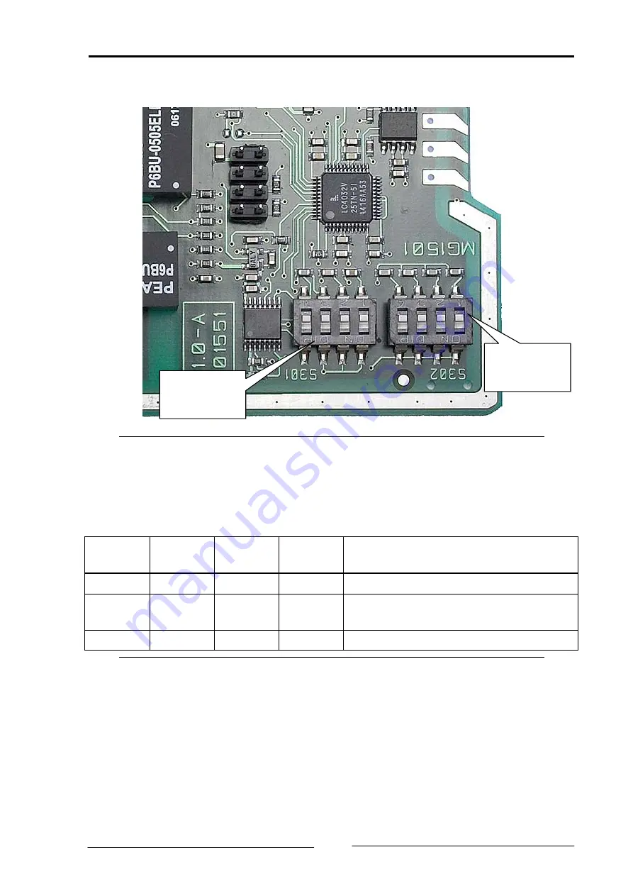
4.2 Configuration of the baudrate (S301) 


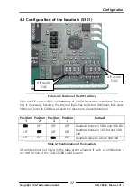
DIP switch 

S302 

DIP switch 

S301 

Picture 4-2 Position of the DIP switches 

With the DIP switch S301 the baudrate of the CAN network is defined. This set-
ting is necessary, because the internal logic has to detect dominant-lock states 

(dominant level on CAN bus exceeds the maximum allowed duration). 
 

Position 

Position 

Position 

Position 

Remark 

ON 

OFF OFF OFF 

Baudrate between 5kBd and 100 kBd 

OFF 

ON 

OFF OFF 

Baudrate between 100kBd and 500 

kBd 

OFF OFF ON 

OFF 

Baudrate equal or above 500 kBd 

Table 4-1 Configuration of the baudrate 

All combinations not listed in the table aren’t allowed. If such a combination is 
set, misfunction of the CAN-CR200 could happen. 

Copyright IXXAT Automation GmbH 

CAN-CR200 - Manual, V1.0

 17 


Summary of Contents for CAN-CR200

Page 1: ...The expert for industrial and automotive communication Manual CAN CR200 Modular CAN repeater ...

Page 2: ...ms with this product or other IXXAT products please contact IXXAT in written form by Fax 49 0 7 51 5 61 46 29 e Mail support ixxat de Copyright Duplication copying printing microfilm or other forms and the electronic distribution of this document is only allowed with explicit permission of IXXAT Automation GmbH IXXAT Automation GmbH reserves the right to change technical data without prior announc...

Page 3: ... P 14 3 2 2 CAN LED 1 2 and 3 15 3 3 CAN bus termination 15 4 Configuration 16 4 1 Configuration of the bus termination resistors 16 4 2 Configuration of the baudrate S301 17 4 3 Configuration of the lock time S302 18 5 Appendix 19 5 1 Technical specifications 19 5 2 Default setting of the bus termination resistors 20 5 3 Default setting of the baudrate S301 20 5 4 Default setting of the lock time...

Page 4: ......

Page 5: ...ures power supply range 9 V 32 V DC two CAN bus interfaces according to ISO 11898 2 galvanically isolated Addition CAN interface via DIN rail bus If several devices are aligned on a DIN rail a star can be achieved High Speed SN65HVD251 CAN socket CAN 1 CAN interface 1 galvanical isolation CPLD High Speed SN65HVD251 CAN socket CAN 2 CAN interface 2 galvanical isolation LEDs High Speed SN65HVD251 CA...

Page 6: ...port work and enable a fast response please provide precise in formation on the individual points and describe your question or problem in de tail If you would prefer to contact our support department by phone please also send a support request via our website first so that our support department has the relevant information available 1 4 Returning hardware If it is necessary to return hardware to...

Page 7: ...r IXXAT devices If an other DIN rail bus is used this one must no be connected to the IXXAT DIN rail bus If this is not considered damages at the connected devices could happen Prior to the connection of device to the DIN rail the TBUS plug has to be mounted on the DIN rail The orientation of the plug has to adapted to the de sired device installation position Guide bar Picture 2 1 TBUS plug and D...

Page 8: ...e are of the DIN rail see Picture 2 4 While the devices are attached to the DIN rail a cor rect mounting to the TBUS plug has to be observed The guide bar of the plug has to mate into the slot in the package Prior to mounting the device it has to be assured that the device is not con nected to power In the Picture 2 5 to Picture 2 6 the mounting of a CAN CR200 is shown Copyright IXXAT Automation G...

Page 9: ...Installation Opening for TBUS plug Picture 2 4 Opening for TBUS plug Picture 2 5 Mounting of the CAN CR200 Slot for the guide bar Copyright IXXAT Automation GmbH CAN CR200 Manual V1 0 9 ...

Page 10: ...t function of the CAN CR200 some EMI points have to be paid attention the DIN rail have to be connected to earth the CAN cable has to be shielded the shield of the CAN cable has to be connected to the Sub D9 and has to be connected on the other device If there are still problems while the CAN CR200 is switched on the distance be tween a source of interference eg motors frequency inverter or a drai...

Page 11: ...nnector For the power connection of the CAN CR200 a screw terminal is used For wir ing please ensure that the cross sectional area of the cable is larger than or equal to 0 2mm The maximum area is 2 5mm for the connector Picture 3 2 Power connector of the CAN CR200 Pin 1 LEDs CAN 2 CAN 1 Power Package lock Copyright IXXAT Automation GmbH CAN CR200 Manual V1 0 11 ...

Page 12: ... the Sub D 9 plugs see Table 3 2 Pin No Sub D9 Signal 1 2 CAN low 3 CAN GND 4 5 6 7 CAN high 9 9 Table 3 2 Pin allocation of the CAN bus connector The shield of the CAN connector is connected to the earth via a 10 nF capacitor The earth of the device is automatically connected to the DIN rail after mounting the device on the DIN rail The ground of the CAN bus interface is connected to earth via a ...

Page 13: ... the DIN rail bus are described in Table 3 3 Pin No Sub D9 Signal 1 CAN high 2 CAN low 3 GND 4 5 Table 3 3 Pin allocation of the DIN rail bus For the DIN rail bus so called TBUS plugs are necessary This plugs were pressed in the DIN rail More detailed information can be read in chapter 2 1 Pin 1 Picture 3 3 TBUS plug with DIN rail Copyright IXXAT Automation GmbH CAN CR200 Manual V1 0 13 ...

Page 14: ...problem with the power sup ply Flashing mode Description Causes Hints Off No power Device not connected to a power supply Fuse of the device damaged Internal power supply damaged green Power ok Device fully functional red Device is resetted After power up the device is set into reset and the LED is red for the duration of the reset The normal duration period is about 200ms Power supply out of orde...

Page 15: ...is triggered red blinking CAN communication but errors The received bits are not equal to the transmitted ones red Dominant lock An external device applies a perma nent dominant level to the CAN Table 3 5 States of the CAN LED 3 3 CAN bus termination The CAN CR200 offers the possibilty to add bus termination resistors to each CAN network connected to the device This feature is realized with a DIP ...

Page 16: ... each CAN circuit a bus termination resistor could be activated by a DIP witch Just one position has to set to ON but to avoid misunderstandings allways both positions should be set to ON CAN 2 CAN 3 CAN 1 Picture 4 1 Position of the DIP switches for the bus termination resistors The bus termination resistors should activated if the CAN CR200 is the first or the last device in the network The term...

Page 17: ...dominant level on CAN bus exceeds the maximum allowed duration Position 1 Position 2 Position 3 Position 4 Remark ON OFF OFF OFF Baudrate between 5kBd and 100 kBd OFF ON OFF OFF Baudrate between 100kBd and 500 kBd OFF OFF ON OFF Baudrate equal or above 500 kBd Table 4 1 Configuration of the baudrate All combinations not listed in the table aren t allowed If such a combination is set misfunction of...

Page 18: ...0 OFF OFF OFF OFF 100 OFF OFF OFF ON 300 OFF OFF ON OFF 500 OFF OFF ON ON 800 OFF ON OFF OFF 1000 OFF ON OFF ON 1300 OFF ON ON OFF 1500 OFF ON ON ON 1800 ON OFF OFF OFF 2000 ON OFF OFF ON 2300 ON OFF ON OFF 2500 ON OFF ON ON 2800 ON ON OFF OFF 3000 ON ON OFF ON 3300 ON ON ON OFF 3500 ON ON ON ON 3800 Table 4 2 Configuration of the lock time For reference values the following settings can be taken ...

Page 19: ...typically 210 ns CAN baudrates 5 kBaud 1 MBaud Housing material Polyamide Dimensions L x B x H in mm 114 5 x 99 x 22 5 Weight approx 300 g Protection class IP30 Operating temperature range 20 C 70 C Storage temperature range 40 C 85 C Relative humidity 10 95 non condensing Galvanic isolation 500 V AC for 1 min EMC test according to DIN EN 55022 1998 A1 2000 A2 2003 Limit class A FCC Rules 47 CFR P...

Page 20: ...g of the baudrate S301 Position 1 Position 2 Position 3 Position 4 Remark OFF OFF ON OFF Baudrate equal or above 500 kBd Table 5 1 Default baudrate setting 5 4 Default setting of the lock time S302 Position 1 Position 2 Position 3 Position 4 Remark OFF OFF OFF ON Lock time 300 ns Table 5 2 Default lock time setting Copyright IXXAT Automation GmbH CAN CR200 Manual V1 0 20 ...

Page 21: ...sistor IXXAT offers a bus terminal resistor as a feed through connector order number 1 04 0075 03000 Picture 5 1 Connections of the CAN bus terminal resistor Picture 5 2 CAN bus termination resistor Copyright IXXAT Automation GmbH CAN CR200 Manual V1 0 21 ...

Page 22: ...the product CAN CR200 with the article number 1 01 0067 44010 complies with the EC directive 89 336 EEC 01 10 06 Dipl Ing Christian Schlegel Managing Director IXXAT Automation GmbH Leibnizstraße 15 88250 Weingarten Copyright IXXAT Automation GmbH CAN CR200 Manual V1 0 22 ...

Page 23: ...ss A digital device pursuant to Part 15 of the FCC Rules These limits are de signed to provide reasonable protection against harmful interference when the equipment is operated in a commercial environment This equipment generates uses and can radiate radio frequency energy and if not installed and used in ac cordance with the instruction manual may cause harmful interference to radio communication...

Reviews: