Configuration
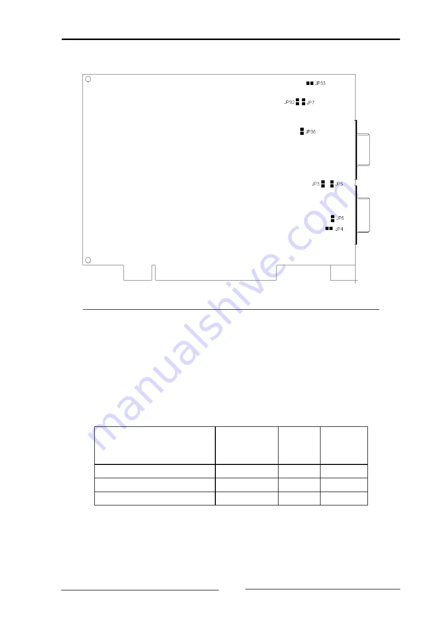
Fig. 3-2: PC-I 04/PCI interface – solder side
3.1.1 Supplying voltage via CAN-plug
With the solder jumpers JP3, JP4, JP5, JP32, JP33 and JP36, VCC (5 V) or GND can
be connected to the CAN-plugs of the two CAN-circuits. For this, the jumpers
given in the following table are to be connected. The solder jumpers are on the
solder side of the PC-I04/PCI.
Plug(X1 / X3)
Pin – Signal
Default set-
ting
CAN-
circuit
1
CAN-
circuit 2
3 / 5 - GND
closed
JP3
JP32
6 / 2 - GND
open
JP5
JP33
9 / 8 - VCC
open
JP4
JP36
Caution:
This voltage may be loaded with maximum 100 mA.
If the bus interface is galavanically isolated, GND and VCC are also galvanically
isolated from the power supply of the PC.
Copyright IXXAT Automation GmbH
PC-I 04/PCI-Manual, Version 1.2
9
Summary of Contents for PC-I 04/PCI
Page 4: ......


