Dimensions
Copyright HMS Technology
Center Ravensburg GmbH
12
USB-to-CAN
V2
-Plugin Manual, V1.2
4 Dimensions
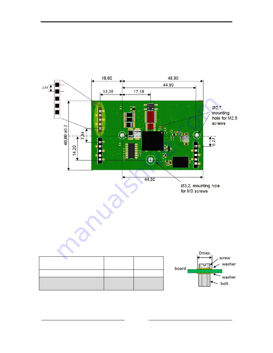
Figure 4-1 shows the mechanical dimensions of the CAN interface. All dimen-
sions in millimeter ± 0.1 if not otherwise noted.
4.1
Overview
Figure 4-1: display (LEDs) on bottom side
4.2
Recommended fastening elements
Using the foreseen mounting holes, fastening elements shown in Table 4-1 are
recommended.
Mounting hole diameter
in mm
2.7
3.2
Dmax in mm
5.0
7.0
Recommended fastening
element
M2.5 x 5
M3 x 6
Table 4-1
Summary of Contents for USB-to-CAN V2
Page 1: ...Hardware Manual USB to CAN V2 Plugin USB CAN Interface...
Page 4: ......


