Connectors and displays
Copyright HMS Technology
Center Ravensburg GmbH
7
USB-to-CAN
V2
-Plugin Manual, V1.2
3 Connectors and displays
3.1
Connectors
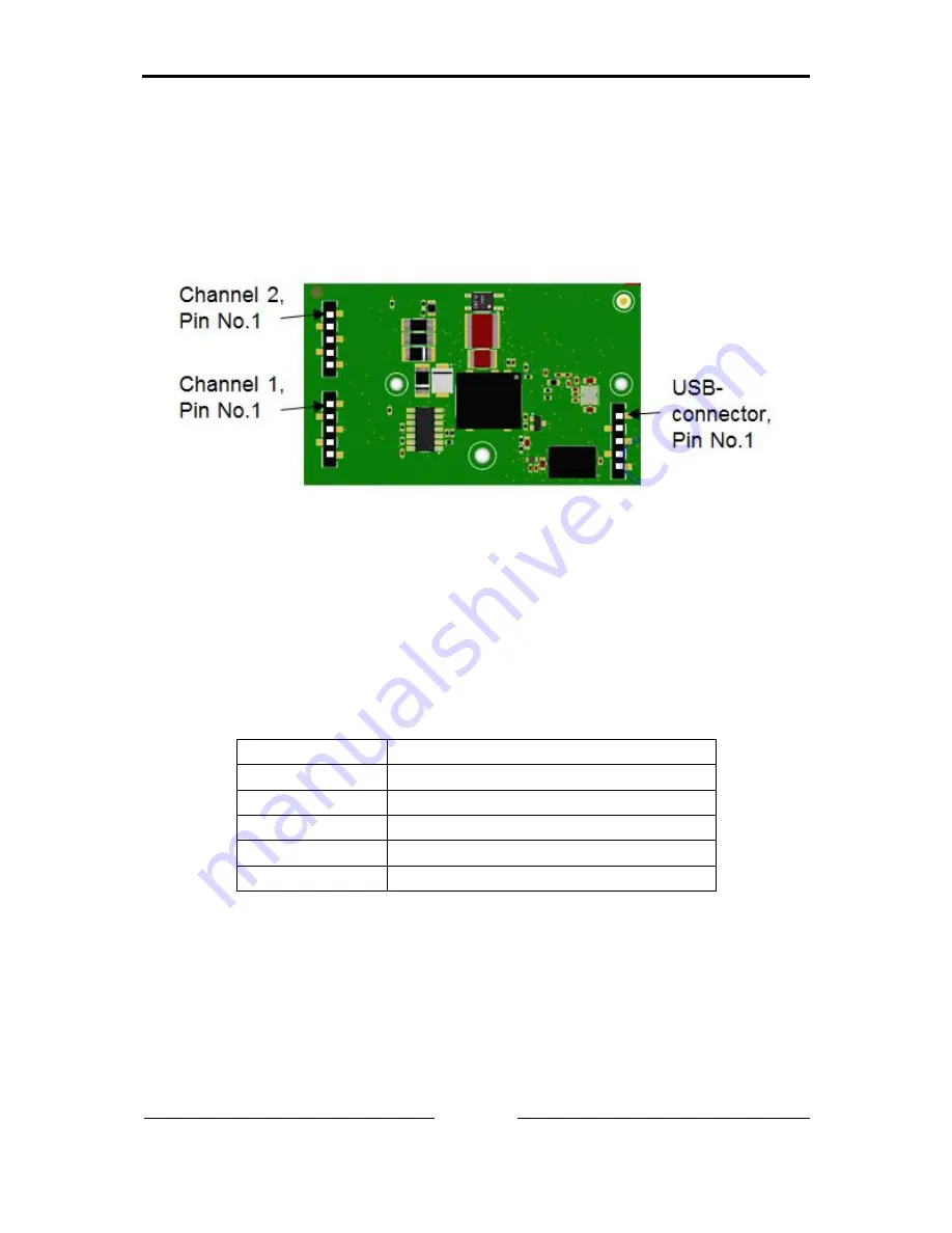
In Figure 3-1 the position of field bus and USB connectors of the CAN Inter-
face with the appropriate pin no. 1 is shown.
Figure 3-1: Displays (LED) on bottom side
3.1.1 USB connector
The shield (pin 5) of the USB cable is connected to ground (GND) using a
100nF capacitor and therefore also connected to ground of the USB plug.
It is recommended, that the interface is directly connected to PC USB ports or
to self powered USB hubs to ensure sufficient power supply.
USB Pin No.
Signal
1
+5V / V / VCC
2
D- / Data - / USB -
3
D+ / Data + / USB +
4
GND / Voltage - / Ground
5
S-GND / Shield
Table 3-1, pinning USB connector
Summary of Contents for USB-to-CAN V2
Page 1: ...Hardware Manual USB to CAN V2 Plugin USB CAN Interface...
Page 4: ......


