89
89
89
89
RADARLINK
OUT
on the first slave unit to the
RADARLINK
IN
connector on the second slave and so on. The
RADARLINK
connectors are located on the right side of the back panel.
Note: The entire length of cabling between the RADAR
24 units must be less than 10 meters (30 feet.).
Software Versions
All units in a RADARLINK
configuration should be running identical versions of software. It is always
recommended that you use the latest versions of RADAR
24 software. You can download the latest software
releases at
www.recordingtheworld.com
.
Note: RADAR
24 and RADAR
II units can be linked together but due to changes and improvements in the
RADARLINK protocol there may be compatibility issues between certain versions of software. Use only the latest versions of
software for both machines. RADAR
24 and RADAR
II software can be downloaded from our website
www.recordingtheworld.com .
ID Numbers
All units connected using the RADARLINK protocol must have an ID number. The unit that initiates
RADARLINK communication is automatically designated the master machine and assigned
M
as its
RADARLINK ID. Each slave must be manually assigned a unique ID.
To assign a RADARLINK ID number to a slave machine:
1. Use
the
MENU/PREV
, arrow keys and
ENTER
key to go to the
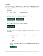
MAIN / SYNC MENU / RADARLINK
menu and press
the
ENTER
key.
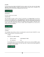
2. Use the up and down arrow keys to select the
RADARLINK ID
dialog from the menu and press the
ENTER
key.
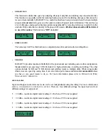
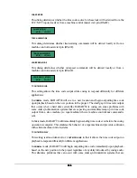
3. Use the up and down arrow keys to select a unique RADARLINK ID between 1 and 7 and press the
ENTER
key.
RADARLINK Enable/Disable
To enable or disable RADARLINK:
1. Press either the
RLINK
or
L
key on the
Session Controller
or use the
MENU/PREV
, arrow keys and
ENTER
key to go to the
MAIN / SYNC MENU / RADARLINK
menu and press the
ENTER
key.
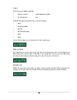
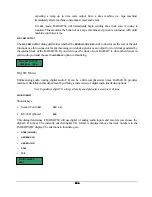
2. Use the up and down arrow keys to locate the
ENABLE
DISABLE
dialog and press the
ENTER
key.
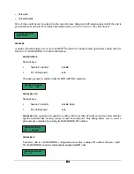
3. Use the left and right arrow keys to select
ENABLE
or
DISABLE
and press the
ENTER
key.
4. Select
YES
at the prompt and press the
ENTER
key.


