background image

Column Use Counter and Invalid Columns

The AFC instrument records the number of times that each smart column has been used. The columns 
are intended to be used

 up to five times.

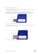
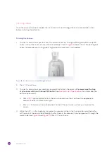
A warning indicator will be displayed when the recommended number of uses is approaching the 
maximum and after this number has been exceeded, as shown below in

 Figure 12.

 The AFC will also 

provide guidance on how many column uses are left before the column becomes invalid.

Figure 12: A warning indicator shows how many uses a column has left.

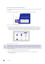
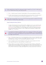
A column will become invalid once it has been used 10 times. The AFC will not run invalid columns, which 
will be indicated as shown below in 

Figure 13.


Figure 13: The home screen displaying the error message when a column has been used 10 times.

Automatic Fraction Collector User Manual

25

Summary of Contents for qEV

Page 1: ...www izon com USER MANUAL AUTOMATIC FRACTION COLLECTOR AFC...

Page 2: ...by the purchaser Izon Science Ltd makes no representations that this document is complete accurate or error free and assumes no responsibility and will not be liable for any errors omissions damage or...

Page 3: ...9 Section 7 Operating Instructions 22 Choosing run parameters 22 Carousel side selection 22 Tube type selection 22 Volume Size Selection 23 Setting up a run 23 Mounting the qEV Column to the AFC Tower...

Page 4: ...e taken Earth ground terminal Direct Current DC Voltage polarity of the jack SETUP Text that appears in pink is used to indicate buttons and sequences that are used on the AFC touchscreen Make sure to...

Page 5: ...is different for each column type Buffer Volume collection position The position in which fluid exiting the column will enter the central well via the central well channel See Figure 3 and Figure 4 C...

Page 6: ...ll is calibrated using the 10 g calibration weight See Section 5 Nozzle The area from which fluid exits the qEV column Nozzle Set The entirety of the nozzle tip a piece of silicon tubing and the adapt...

Page 7: ...skin Please review the following guidelines and precautions prior to each use of the qEV column especially if flushing with an antimicrobial buffer before storage recommended Prevention Do not get in...

Page 8: ...r mouth nose and eyes Completely protect any cut or abrasion before working with potentially infectious or hazardous material Wash your hands thoroughly with soap and water after working with any pote...

Page 9: ...ower adaptor double insulation Use only the power supply unit provided with this product Specification of unit is detailed in Table 3 The AFC system is to be installed indoors and positioned away from...

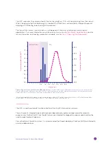
Page 10: ...elution washout and regeneration of the columns The AFC manages the collection of fractions from the column by automatically differentiating between the buffer volume pink area in Fig 1 and the volum...

Page 11: ...mn are intended for diagnostic purposes and should not be used to make treatment decisions For verification of the entire system it is recommended that Good Laboratory Practices GLP be followed to ens...

Page 12: ...Plate 7 qEVoriginal Reservoir 8 5 0 mL Collection Tube x15 9 2 0 mL Collection Tube x30 10 12 volt Power Supply 11 Power Lead 12 USB 2 0 Type A to USB 2 0 Micro cable male to male 13 10 g Calibration...

Page 13: ...This side can be used with the qEVsingle qEVoriginal qEV1 or qEV2 Note some collection tube brands will not fit properly into the AFC carousel We recommend ordering 2 mL and 5 mL Axygen tubes Product...

Page 14: ...d be within the operational temperature of 18 24 C 65 75 F Use a buffer with an ionic strength of 0 15 M or greater to avoid any unwanted ionic interactions between the solute molecule and the matrix...

Page 15: ...ming into contact with any spills or fluid General Operating Procedures For indoor use only and to be used within the rated conditions noted in system specifications Take care not to spill any fluids...

Page 16: ...he power switch at the rear The screen will light up briefly showing the IZON logo and the carousel will rotate to its zero position Ensure the valve is in place as shown Figure 5 below Figure 5 AFC v...

Page 17: ...will be on the right of the central well channel For the other side of the carousel that holds 5 mL tubes the flush hole is on the left of the central well channel 4 Once the flush hole has been alig...

Page 18: ...4 Once the measurement is complete the lighting will change to green and the screen will instruct the user to place the 10 g calibration weight onto the centre of the empty carousel 5 Ensure that the...

Page 19: ...r 2 0 mL 1 5 or 2 0 mL 5 0 mL qEV SPECIFICATIONS 6 Choosing the right qEV column to run will depend on the volume of the sample and the target isolation range of the analyte Table 5 qEV Legacy Column...

Page 20: ...sive of an additional 0 25 mL from the buffer volume inside the nozzle set Column Type qEVoriginal qEV1 Optimal Sample Loading Volume1 500 L 1 mL Reusability Yes up to 5 times Yes up to 5 times Column...

Page 21: ...see Fig 8 Table 7 Specifications of qEV 35nm and qEV 70nm Series Figure 8 Comparison of total protein elution levels and recovery of 57 nm particles between a qEVoriginal 35nm Legacy and a qEVoriginal...

Page 22: ...ion on the carousel has been filled and then wait for you to replace the tubes on the carousel Tube Type Selection Each side of the carousel is designed to hold a specific tube size The carousel side...

Page 23: ...strument 1 Turn on the instrument by switching on the power button at the rear of the instrument 2 Before a column has been inserted or if a column without an RFID tag has been inserted the tower ligh...

Page 24: ...he AFC tower as shown in Figure 10 below Figure 10 A qEV original 70nm Legacy column loaded correctly onto the AFC Ensure that the IZON logo is facing away from the AFC tower 6 Turn the column within...

Page 25: ...as been exceeded as shown below in Figure 12 The AFC will also provide guidance on how many column uses are left before the column becomes invalid Figure 12 A warning indicator shows how many uses a c...

Page 26: ...t collection size and buffer volume size as shown in Figure 15 below To change the adjusted buffer volume from the default value deselect the DEFAULT BV button Figure 15 The Collection Schedule menu T...

Page 27: ...ntation 2 Ensure that you have loaded enough tubes for your collection protocol 3 Gently place the carousel onto the carousel plate Ensure that the carousel alignment hole engages with the raised caro...

Page 28: ...The next screen will ask you whether you would like to flush the column We recommend flushing of all columns with fresh filtered PBS buffer See Section 6 qEV Specifications for information on buffer...

Page 29: ...OK to continue It is important to only load the sample at this point let it run through until the flow stops and then top up the reservoir with the appropriate amount of buffer displayed on the screen...

Page 30: ...nother run without cleaning This is not recommended Remember to empty and clean out the carousel central well between consecutive runs 14 Select YES to be guided through the cleaning process before be...

Page 31: ...via the instrument s touchscreen 2 AFC Software Updater this is a software package that is used to update the AFC Operating Software it is run on a computer with Windows 10 OS that is connected to the...

Page 32: ...GET UPDATE to download the latest version of the AFC Operating Software Updating the AFC Operating Software To update the AFC Operating Software the AFC must be connected to a computer with the AFC S...

Page 33: ...software update is complete disconnect the USB cable and close the AFC Software Updater Maintenance of AFC Instrument Calibration Testing It is recommended to periodically test the load cell calibrat...

Page 34: ...FC tower Figure 21 Pinch valve cover on Figure 22 Pinch valve cover removed Pull tube laterally 2 Firmly grasp the nozzle tube above and below the pinch valve and gently pull away laterally until the...

Page 35: ...rge from the hole in the pinch valve cover and be visible once the cover has been replaced as shown in Figure 26 a If the tip is hidden behind the pinch valve cover then the tube has been inserted too...

Page 36: ...al number and compliance sticker Figure 26 Nozzle tip fully emerging through the hole in the pinch valve cover When reporting AFC issues to support izon com please provide the serial number of the AFC...

Page 37: ...ted into the Luer lock Check the tubing is fully pushed into the valve Remove the valve cover and inspect the tubing replacement parts can be found in the consumables box Dripping from the nozzle when...

Page 38: ...the valve head Droplets are catching on the carousel during the flushing procedure Carousel is not aligned correctly Nozzle is bent Recalibrate the carousel alignment to the centre of the flush positi...

Page 39: ...rmance This device complies with part 15 of the FCC Rules Operation is subject to the following two conditions 1 This device may not cause harmful interference 2 This device must not accept any interf...

Page 40: ...Visit www izon com for more information FIND OUT MORE...

Reviews: