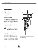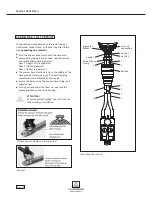
If the controls were delivered at the same time but
unattached, connect them as follows (see also illustra-
tion
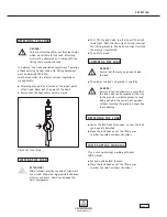
Connecting the controls
):
Push the one-ear hose clamp onto the hose ends.
Grease hose grommets and connect control hoses to
the corresponding hose grommets.
Hose 1 (supply air) to grommet 1
Hose 2 (lift) to grommet 2
Hose 3 (lower) to grommet 3.
The one-ear hose clamp must lie in the middle of the
hose grommet clamping range. The best clamping
characteristics are achieved in this range.
Secure the hoses using the one-ear hose clamps and
crimping tool.
Push up bellows and allow them to snap into the
groove provided on the valve housing.
AT T E N T I O N !
To ensure perfect sealing, the
˝
ear˝ must be
fully closed on installation.
Removal
Connecting the controls
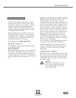
Pinched one-ear clamp and crimping tool
C O N N E C T I N G T H E CO N T RO L S
powered by air !
I N I T I A L O P E R AT I O N
Page 20
main air
connection
nozzle 1
nozzle 2
1
2
1
2
1
2
bellows
groove for
bellows
nozzle 3
one-ear hose
clamp
3
3
3
Summary of Contents for JDN mini 1000
Page 47: ...powered by air NOTES Page 47 ...

