I N I T I A L O P E R AT I O N
Page 20
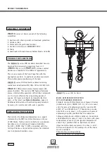
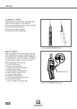
C O N N E C T I N G T H E R O P E C O N T RO L S
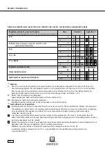
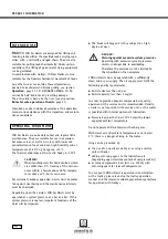
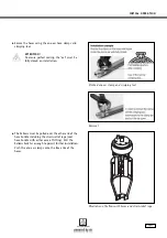
Knot both control ropes at the ends of the
control lever.
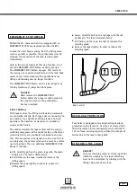
Knot the green pin into the rope which activates
"lift" mode, with the pointed end upwards.
(See also illustration
Rope control
page 31)
Knot the yellow pin into the rope which activates
"lower" mode, with the pointed end downwards.
Knot the handle into the rope so that the arrow
markings correspond to the actual direction of
movement.
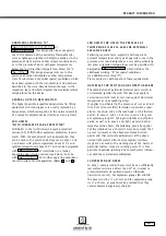
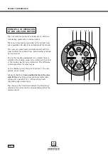
E - CO N T R O L CO N N E C T I O N
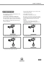
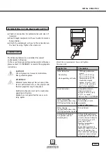
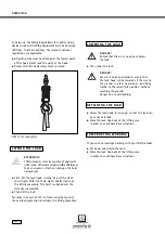
Pushbutton valve (hand control)
Guide the strain-relief rope through the eye on the
pushbutton valve and secure using the rope clamp.
Push the one-ear clamps onto the hose ends.
Attach the hoses to the hose nipples.
The one-ear hose clamp must lie in the middle of
the hose nipple clamping range. The best clamping
characteristics can be achieved in this range.
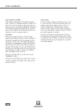
Pushbutton valve with nipples and rope with
designation lift and lower
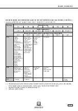
Rope control, motor side
C O N N E C T I N G T H E C O N T R O L S


