I N I T I A L O P E R AT I O N
Page 24
AT T E N T I O N !
The control hoses must not be subject
to tensile load; adjust the strain-relief
ropes accordingly.
Pull the bellows over the hose adapter and secure via
the central bolt, (see page 22, bottom).
C O N V E R S I O N F R O M E T O F I
Removal of E-controls as previously described (page 23).
Installation of FI-controls
Pull the bellows over the hose bundle for FI-control.
Remove approx. 80 mm of hose bundle protective
sheathing.
Screw the "straight screw connections" (Steck-fix) for
4 mm hoses into the hose adapter (A/F 16).
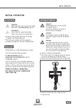
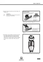
With this type of control, strain-relief of the hand
controls is via the protective sleeve of the hose bundle.
For this purpose, the protective sleeve is pushed onto
the hose carrier and is secured using a one-ear clamp.
Installation facilitation:
Heat the protective sleeve
(hose sheathing) with a hot-air gun and grease the
hose carrier.
Slightly bend open the ring of the eye bolt in order
to attach the hose carrier.
Close the ring again to prevent detaching.
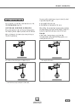
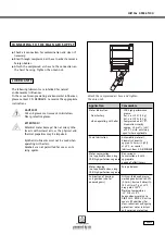
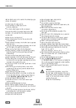
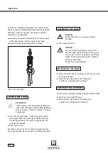
Insert the control hoses:
See illustration on page 22, top.
Compressed air
with hose designation 1 or colour: white
Movement direction "lift"
hose designation 2 or colour: green
Movement direction "lower"
hose designation 3 or colour: red
AT T E N T I O N !
The control hoses must not be subject to
tensile load; adjust the strain-relief
ropes accordingly.
Pull the bellows over the hose adapter and secure via
the central bolt, (see illustration on page 22, bottom).
CONVERSION FROM AIR CONTROL TO ROPE CONTROL
AT T E N T I O N !
Only air controls without upstream mainstream
valve can be converted to rope control.
Removal of air controls
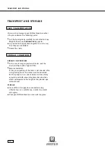
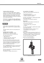
Remove the hose adapter (secured by central bolt).
For removal of the hose adapter, a long A/F 6 socket
spanner must be guided through the middle of the bel-
lows and inserted into the hexagon socket of the bolt,
(illustration on page 22, below).
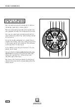
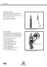
The cover
"1"
in the axis centre must be removed
(M 6 bolt, A/F 5).
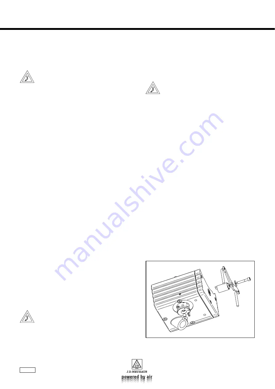
Installation of rope controls
The connecting surface of the hose adapter on the valve
housing is closed off with a disc, (from conversion kit
Art. no.: 13590, item 10) and is secured with the
M 8 x 16 countersunk screw (item 50).
The dowel pin (roll pin, item 70) must be inserted in
the bore
"2"
provided.
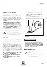
Insert the rope control lever connector (item 20) into
the cover bore with the lug
"3"
facing upwards; push
on the control lever (item 30) and secure with the
M6 x 35 bolt (item 40) and washer (item 60).
Guide the control ropes
"4"
through the bores
"5"
in
the lever and knot them. Rope colour: "green" lift,
"red" lower. Further, see section
Connecting the rope
controls
, page 20.
Installation of rope controls

