M
AINTENANCE
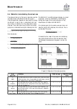
Adjusting overload protection
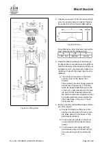
The adjustment
method described here is based on the attach-
ment of test loads (
,
→
Figure 14). The overload
protection is located in the control valve.
1. Attach overload of 125% of the load capacity.
2. If this overload is lifted, the adjusting bolt
(1)
must be adjusted clockwise until it is no
longer possible to lift the overload. If the over-
load is not lifted, the adjusting bolt must be
adjusted anticlockwise until it is possible to
lift the overload. Then it must be adjusted
back until it is no longer possible for it to lift
the overload.
3. After the adjustment process, it must be pos-
sible to lift 110% of the nominal load. A dy-
namic overload test of 110% of the nominal
load is therefore possible.
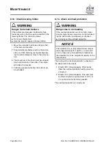
Figure 14: Adjusting overload protection
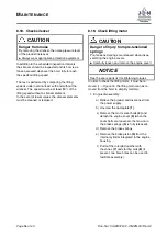
8.14. Check chain
WARNING
Danger from chain fracture
If the chain of your product
PROFI 25 TI
has one
of the features listed below, the chain may break
upon further use.
I
Do not use the product
I
Replace the chain
•
Corrosion pitting
•
Bent or damaged chain links
•
Chain drawn tight
•
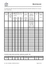
Wear over 11 pitches (dimension A)
•
Single pitch wear (dimension B)
•
Diameter reduction of a chain link (dimension
C)
•
Elongation of a chain link (dimension D)
Check the entire length of the chain. When check-
ing the replacement limit, future wear up until the
next inspection date must be taken into account.
If the chain dimension values are outside the limit
values specified in the table when checked, the
chain has reached its replacement limit and must
be replaced by a new one.
The chain sprockets must also be replaced to-
gether with the chain, as otherwise the new chain
will be subjected to increased wear. Each chain
replacement must be documented in the inspec-
tion log.
Please observe the information contained in
,
→
DIN 685, Part 5
,
→
ISO 7592
Doc.-No.: VA049318-10-OM-EN-0319-64-2
Page
53
of 64

