M
AINTENANCE
d) Coat the vanes lightly with high-
performance grease and insert into the
rotor slots with the starting aids.
e) Coat the entire braking piston surface, in-
cluding the brake piston seal, lightly with
high-performance lubricant and push
the brake piston into the internal cylinder
with the braking surface first. Note the
position of the eccentric bore.
f) Insert the brake springs into the bores of
the brake piston.
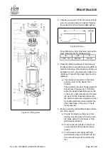
g) Loosen adjustment bolts
(14)
and lock
nuts
(15)
. Screw back adjusting bolts
sufficiently.
h) Apply high-performance grease lightly to
rotor bearing (needle bush) in the motor
cover and install motor cover. Ensure
correct seating of the brake springs and
the locating pins to the motor housing
and to the brake piston.
i) Do not tighten the four adjusting bolts
after bolting the motor cover in place,
only screw them in loosely by hand to the
stop in the cover. Screw back the lock
nuts sufficiently beforehand.
j) Then screw back the adjusting bolts
45
◦
from the stop, hold and lock with
the nuts. For lifting heights of 10 metres
(33 feet) and more, a setting of up to 60
◦
may be required. For operation in areas
with ambient temperatures exceeding
30
◦
C (86
◦
F), the adjustment must be
carried out with the device warmed up
accordingly.
k) Tighten the nameplate
(1)
.
5. Check the braking action under nominal load
(run in the brake by performing several hoist-
ing cycles, then assess) prior to initial opera-
tion. Check the motor power. In the event of
low motor power, regulate the adjusting bolts
again.
8.20. Replace chain
WARNING
Danger from chain fracture
The chain is subjected to impermissible stresses if
the chain is twisted.
I
Do not twist the chain!
NOTICE
JDN chains are matched in close tolerances to
the sprocket. In order to ensure an optimum func-
tion of the chain and in order to prevent dangers,
only genuine JDN chains may be installed.
NOTICE
If the chain end link of the load chain is positioned
incorrectly, it must be removed. The following
chain link will then be positioned correctly.
The spare parts list contains information about
torques and other representations of the indi-
vidual components.
1. Loosen the chain from the dead end chain
mount
(9)
.
2. Remove components on the idle
(1)-(3)
:
a) Loosen the clamp.
b) Remove the components
(1)-(3)
from the
chain.
3. Loosen the chain from the load chain attach-
ment
(5)
.
4. Attach the new chain to the end link of the
load section of the old chain after aligning the
welds and the first chain link by means of an
open chain link. The welds of the old and new
chain must have the same orientation.
5. Switch
PROFI 25 TI
to Lifting and run the new
chain through the bottom block and drive
chain sprocket. After it exits, take the old
chain and open chain link from the new chain.
6. Align the chain and fasten the chain end link
(5)
by means of the chain end link bolt (po-
sition of the weld must align with that of the
following links). If necessary, the last chain
link must also be separated.
Page
58
of 64
Doc.-No.: VA049318-10-OM-EN-0319-64-2

