P
RODUCT INFORMATION
3.5.5. Motor lubrication
The JDN high performance grease contained in
the motor allows for operation with oil-free com-
pressed air.
It works over an operating time of about 250 hours
and should, however, be replaced as required, but
after five years at the latest.
3.5.6. Control
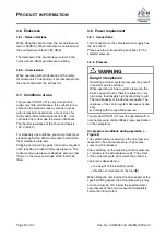
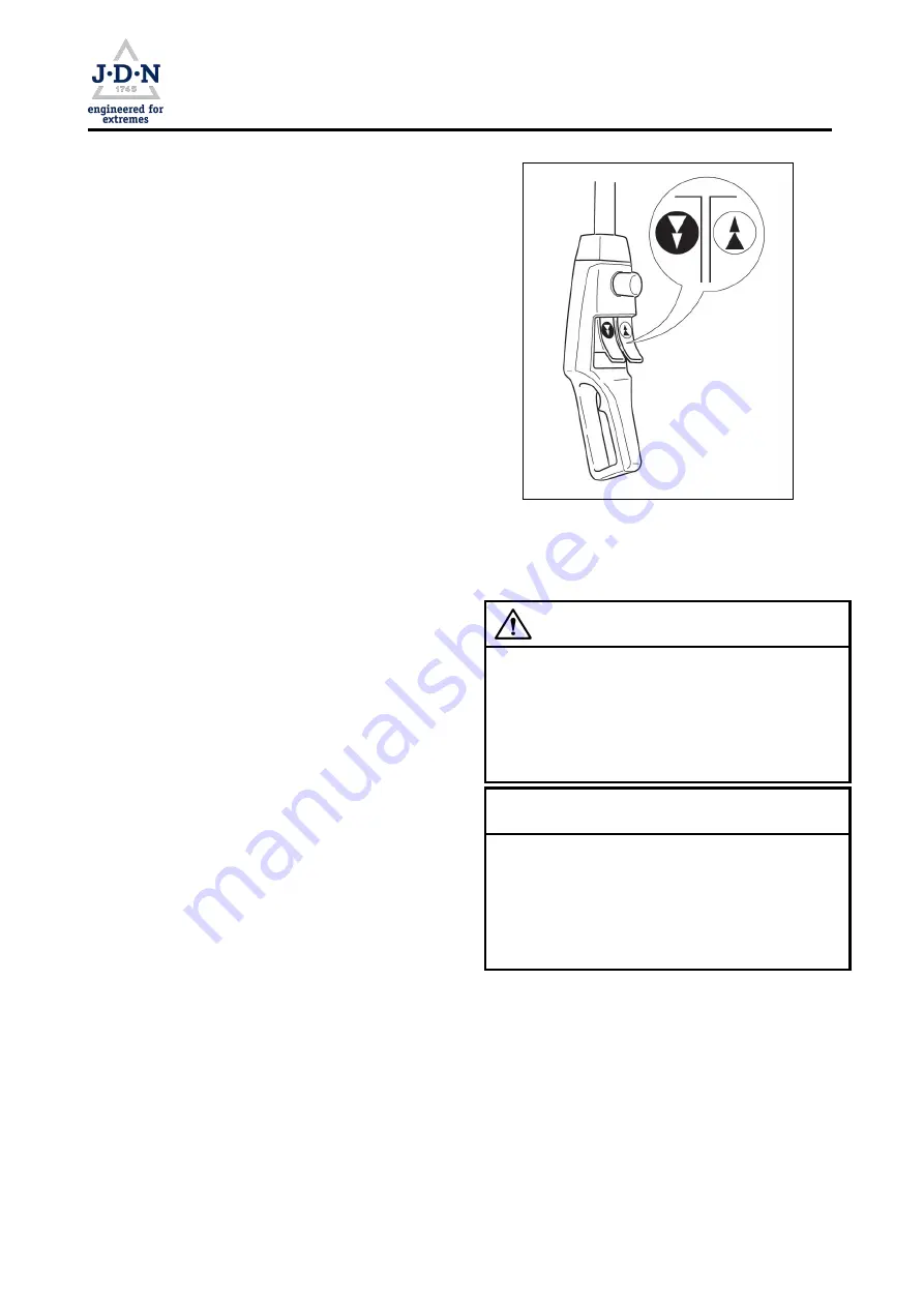
With FI control (
,
→
Figure 5), the lifting and low-
ering motion can be regulated via two adjacent
push buttons. In the process, the control pressure
is continuously adjustable so that a sensitive po-
sitioning of the load is possible. The direction of
movement of the load hook is indicated by arrows
on the push buttons.
I
Lifting: Gently push down the right push but-
ton. The load will be lifted slowly.
I
Depress the push button further to increase
the lifting speed.
I
Ease up on the push button slightly to reduce
the lifting speed.
I
Lowering: Gently depress the left push button.
The load will be lowered slowly.
I
Depress the push button further to increase
the lowering speed.
I
Ease up on the push button slightly to reduce
the lowering speed.
The control system is suitable for use in explosive
areas.
All control switches automatically return to the
neutral position when released. All movements are
stopped instantaneously and the load is securely
held in its current position.
3.5.7. EMERGENCY STOP device
Your control system is equipped with an EMER-
GENCY STOP device.
By pressing the red EMERGENCY STOP button,
a separate blocking valve closes and your product
PROFI 3 TI
instantly comes to a halt and the load
is held securely in its current position. The control
system is now inoperable.
Figure 5: Control
3.5.8. Lifting limiter
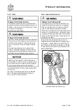
WARNING
Danger from chain fracture
If the buffers are damaged, unacceptably high
loads may act on the chain when starting the
lifting limiter. The chain may break.
I
Do not use product
I
Have product repaired (replace buffer)
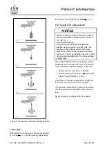
NOTICE
The lifting limiter may only be started in cases of
emergency. The operator must monitor the load
hook movement and stop the lifting movement in
due time. Striking the buffer against the housing
is to be avoided. This may result in damage to the
buffers.
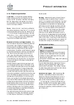
Your product is equipped with a limiter that stops
the lifting movement (
,
→
Figure 6).
In order to achieve a limitation of the lifting move-
ment, a buffer
(1)
is mounted to the bottom block /
load sleeve. If the buffer is moderately deformed
in the boundary layer, the overload protection
switches the motor off.
Doc.-No.: VA053957-40-OM-EN-0720-60-2
Page
15
of 60


