M
AINTENANCE
8.6.3. Re-lubricate the lifting motor
CAUTION
Danger of injury from pre-tensioned
springs
Pre-tensioned springs are released when disas-
sembling the engine covers.
I
Carefully loosen and remove the engine cover!
NOTICE
The grease filling in the rotor chambers is suffi-
cient for approximately 250hours under normal
operating conditions. The rotor chambers only
empty to approximately 60%. In this condition,
refilling must be performed.
NOTICE
See the spare parts list for tightening torques
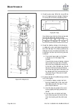
In order to re-lubricate the motor, it must be re-
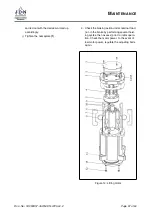
moved (Abbildung (
,
→
Figure 14, the lifting motor
can be removed from the hoist to simplify matters):
1. Engine disassembly:
a) Relieve the product and disconnect from
the power supply.
b) Unscrew the nameplate
(1)
.
c) Remove the motor cover bolts
(2)
and
detach the engine cover
(3)
(when the
cover bolts are loosened, the tension in
the brake springs
(4)
is fully released).
d) Remove the brake springs.
e) Remove the brake piston
(5)
from the
internal cylinder integrated in the engine
housing. If present, bore holes can be
used to facilitate assembly.
f) Pull out the rotor
(6)
htogether with
vanes
(7)
and starting aids
(8)
.
2. Renewing motor lubrication:
The retaining rings
(9)
and Vyon washers
(10)
must be removed in order to refill the lubrica-
tion chambers of the rotor. Then fill the lubri-
cant chambers with high-performance lubri-
cant (JDN item. no 11904) without forming
cavities! Use new Vyon washers to close off
the lubricant chambers and secure these us-
ing retaining rings.
3. Engine assembly with additional basic lubrica-
tion of the engine:
a) Provide the braking surface and rotor
bearing (needle bush) of the cover with
the brake pad with a thin layer of high-
performance lubricant.
b) Coat the internal cylinder of the motor
housing lightly with high-performance
grease
c) Coat the entire rotor lightly with high-
performance grease and insert into the
front rotor bearing with the clutch side
first.
d) Coat the vanes lightly with high-
performance grease and insert into the
rotor slots with the starting aids.
e) Coat the entire braking piston surface, in-
cluding the brake piston seal, lightly with
high-performance lubricant and push
the brake piston into the internal cylinder
with the braking surface first. Note the
position of the eccentric bore.
f) Insert the brake springs into the bores of
the brake piston.
g) Loosen adjustment bolts
(14)
and lock
nuts
(15)
. Screw back adjusting bolts
sufficiently.
h) Apply high-performance grease lightly to
rotor bearing (needle bush) in the mo-
tor cover and install motor cover. Ensure
correct seating of the brake springs and
the locating pins to the motor housing
and to the brake piston. Do not tighten
the four adjusting bolts after bolting the
motor cover in place, only screw them in
loosely by hand to the stop in the cover.
Screw back the lock nuts sufficiently be-
forehand.
i) Then screw back the adjusting bolts
45
◦
from the stop, hold and lock with
the nuts. For lifting heights of 10 metres
(33 feet) and more, a setting of up to 60
◦
may be required. For operation in areas
with ambient temperatures exceeding
30
◦
C (86
◦
F), the adjustment must be
Page
46
of 60
Doc.-No.: VA053957-40-OM-EN-0720-60-2


