67
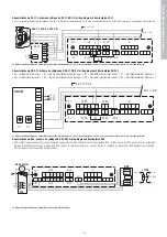
4. Aansluitschema VG 31, Schéma de câblage du VG 31, VNG 31 wiring diagram, Stromlaufplan VG 31
• VG 31 toepassen in combinatie met schakelaar SAG, VG 31 utilisé avec un interrupteur SAG, VG 31 used in combination with a SAG switch, VG 31 verwenden in Kombination mit Schalter SAG.
A = Motor aansluiting, Câblage du moteur, Motor connection, Motoranschluss B = Deze lussen verwijderen, Retirer ces boucles, Remove these links, Diese Schleifen entfernen
5. Aansluitschema DNG 31, Schéma de câblage du DNG 31, DNG 31 wiring diagram, Stromlaufplan DNG 31
• R1 = instelpotmeter toerental = 1, R1 = régime du potentiomètre de réglage = 1, R1 = adjustable potentiometer speed = 1, R1 = Einstellpotentiometer Drehzahl = 1
• R2 = instelpotmeter toerental = 2, R2 = régime du potentiomètre de réglage = 2, R2 = adjustable potentiometer speed = 2, R2 = Einstellpotentiometer Drehzahl = 2
A = Motor aansluiting, Câblage du moteur, Motor connection, Motoranschluss B = Deze lussen verwijderen, Retirer ces boucles, Remove these links, Diese Schleifen entfernen
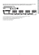
6. Aansluitschema RSC, Schéma de câblage du RSC, RSC wiring diagram, Stromlaufplan RSC
• RSC contact toepassen voor het schakelenvan de servomotor zodra de ventilator wordt ingeschakeld. RSC - Utiliser le contact RSC pour piloter le servomoteur
dès que le ventilateur est mis en marche. Use RSC contact to switch servomotor as soon as the fan is switched on. Einsatz des RSC-Kontakts zum Schalten
des Servomotors bei Einschalten des Ventilators.
A = Motor aansluiting, Câblage du moteur, Motor connection, Motoranschluss
PE1
KL 2B
KL 3B
KL 4
KL 2A
KL 3A
KL 1
L
N
RS
A
RS
B
RS
A
RS
B
An
GND
U3
Ö
G
S
G
EN
EN
1
6
1
2
2
1
1
2
6
1
2
1
18 V E
ist
GND
U3 10 V
E
soll
GND
U3
A
RSC
KL 4-2
KL 4-1
KL 6
KL 2
KL 4-1
KL 4-2
KL 6
250 V/8 A
KL 2
• RSC
LN
Servo motor
M
1
3
5
2
4
6
WS
3 X 0,75 mm2
DNG 31
P 1
P 2
B
PE 1
KL 2B
KL 3B
A
KL 4
KL 3A
KL 2A
KL 1
18 V
E
ist
GND
U3
10 V
E
soll
GND
U3
Ö
G
G
S
EN
EN
L
N
RS
A
RS
B
RS
A
RS
B
An
GND
U3
1
6
1
2
1
2
1
6
1
2
1
2
Max. 31 MXs
10 V
GND
GND
EN
EN
E
E
soll
soll
230 V
50 Hz
L
N
PE1
KL 2B
KL 3B
KL 4
KL 2A
KL 3a
KL 1
L
N
RS
A
RS
B
RS
A
RS
B
An
GND
U3
Ö
G
S
G
EN
EN
1
6
1
2
2
1
1
2
6
1
2
1
18 V
E
ist
GND
U3 10 V
E
soll
GND
U3
A
10 v
GND
GND
EN
EN
E
soll
E
soll
VG 31
L
N
203 V
50 Hz
GND
EN
+ 10 V
E
soll
SAG 0-2, SAG 0-5, SAG 0-M
+10V
EN
E
soll
GND
3 x 0.75 mm
2
Max. 31 MXs
B
Bijlagen,
Anne
x
es,
Appendices,
Anlagen


