background image

10

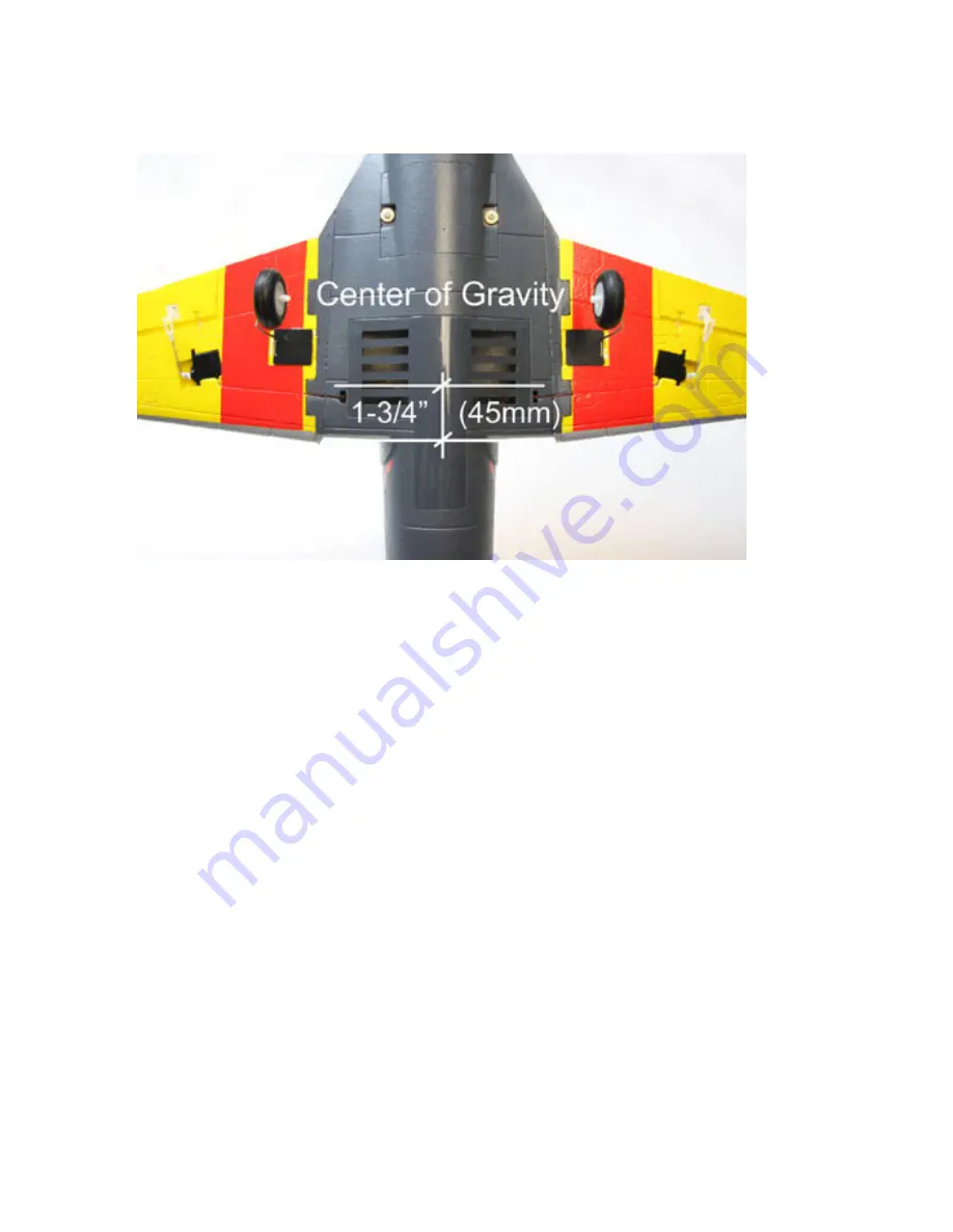
20. The Center of Gravity for the F9F Panther is 1-3/4” (45mm) back from the leading edge

      of the wing where it meets the fuselage. Adjust the position of the battery to achieve correct

      balance. Never attempt to fly a model that is not correctly balanced.


Preparation before flight

21. Set throttle to the lowest position and set transmitter trims to neutral. 


22. Turn on the transmitter


23. Connect the flight battery to the ESC. After ESC initializes check that the correct chan-

nel is

      controlling each control surface and that they are traveling in the correct direction when

      commanded. Example: right stick moved to the right and the aileron on the right wing

      moves upward while the aileron on the left wing moves downward.

24. Adjust each control surface to its neutral position by mechanically adjusting each clevis. 

Recommended control throws for F9F Panther

Elevator

Low Rates 3/16” Up and Down

High Rates 5/16” Up and Down

Aileron

Low Rates 3/8” Up and Down

High Rates 1/2” Up and Down

After initial flights adjust the cotrol throws to best suit your flying style and ability.

Summary of Contents for F9F Panther

Page 1: ......

Page 2: ...chase This does not affect your statuary rights This warranty is not valid for any damage or subsequent damage arising as a result of a crash misuse modification or for damage or consequential damage...

Page 3: ...ght to the battery Do not impact or throw the battery Safety Precautions 1 Please do not change any part of the plane without checking with J Perkins Dist Ltd You will be responsible for any damages c...

Page 4: ...enuine Deans Ultra Connector 30A ESC w BEC and genuine Deans Ultra Connector 3pcs 9g Servo Optional Landing Gear Sold Separately w steerable nose wheel and servo included Required but not included Rad...

Page 5: ...lot for the horizontal stabilizer and glue it in place Repeat for other side 4 Check that horizontal stabilizers are 5 Apply 5 minute epoxy to the root of at 90 degrees to the fin one wing panel 6 App...

Page 6: ...h the foam insert on the right side removed 10 Carefully install the vertical stabilizer onto the fuselage making sure the elevator tube goes into the exit slot Be sure not to foul the pushrod opening...

Page 7: ...position tighten the connector screw on the servo horn with a screwdriver 13 Apply 5 minute epoxy to the nose cone and attach it to the fuselage making sure it is aligned properly 14 The hatch has ma...

Page 8: ...minute epoxy 16 Installing the optional landing gear sold separately Remove the plastic covers on the wings Use 5 minute epoxy to install the plastic landing gear base Next feed the steering servo wir...

Page 9: ...position to achieve proper center of gravity 18 Aileron control throws are 3 8 Up and Down on Low Rates They are 1 2 Up and Down on High Rates 19 Elevator control throws are 3 16 Up and Down on Low R...

Page 10: ...itializes check that the correct chan nel is controlling each control surface and that they are traveling in the correct direction when commanded Example right stick moved to the right and the aileron...

Page 11: ...d and land into the wind Flight Adjustment 1 On initial flight climb to about 75 100 feet and see if any trim is required If the model rolls to the right apply some left aileron trim to level the wing...

Page 12: ...12 J Perkins Distribution Lenham UK www jperkinsdistribution co uk...

Reviews: