background image

650 System Manual (Draft) 
Version 0.4 August 20, 2008 
 

23

bits of COM5, and the drawer open/close status will be reflected on the CTS and RI bits, 
either bit may be used. This virtual COM port driver is designed to work the same as 
most serial cash drawers so that drivers for a serial cash drawer should work if mapped to 
the correct COM port, normally COM5 in the 650 system. 
 
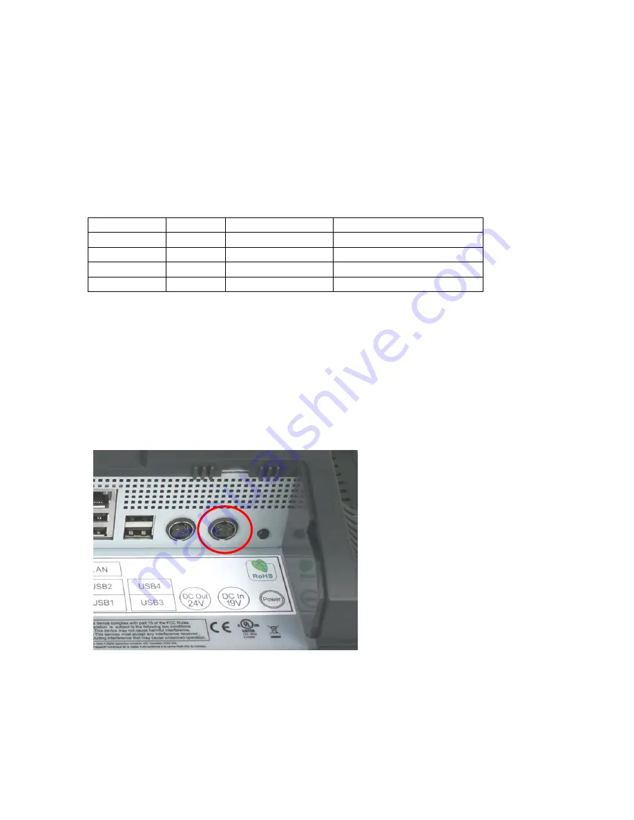
The cash drawer can directly be accessed through two I/O ports, 280 hex and 281 hex. 
Port 280 hex is an output only port and fires the cash drawer when toggled.  
Port 281 hex is and input only port and read the status of the cash drawer.  
 

Cash drawer I/O ports 
Port 

Function  Set to One 

Set to Zero 

280 hex bit 4  Write 

Normal state 

Fire cash drawer 1  (once) 

280 hex bit 5  Write 

Normal state 

Fire cash drawer 2 (once) 

281 hex bit 0  Read 

Drawer 1 is closed Drawer 1 is open 

281 hex bit 1  Red 

Drawer 2 is closed Drawer 2 is open 


Power Supply 

The 650 uses a notebook type power supply that is normally mounted in the base of the 
unit.  The power supply is rated with an output of 19 VDC 7.1 Amps and has an input 
rating of 100-240VAC at 50~60Hz 2.2Amps maximum.  The power supply typically has 
an efficiency rating of 85% under light loads and 90% under heavy loading.  The power 
supply connector is a four pin locking type that plugs into the system’s power input 
connector located in the cable well. 
 

Power Input connector 

Summary of Contents for Integrated Touchscreen Computer J2 650

Page 1: ...J2 650 Integrated Touchscreen Computer System Manual August 2008 ...

Page 2: ... 11 Configurations 11 Processor Support 11 Processors currently supported on the 650 12 I O Ports 13 Off On Button 13 Hard Disks 14 Compact Flash 15 Touch Screen 15 System Board 16 LCD Display 16 Secondary Display Port 17 PS 2 Keyboard port 17 Serial ports 18 Parallel Port 19 USB ports 19 Ethernet Connection 20 Kensington Security Slot 20 Audio 21 Printer Power Port 21 Cash Drawer Ports 22 Power S...

Page 3: ... Auto Mode 40 Restore on AC Power Loss 41 2nd Display D SUB15 19V Out 41 Run PXE ROM 41 Display OEM Logo 42 RTC Configuration 42 Wake On LAN 43 CMOS Clear 43 Boot Settings 43 Exit Options 45 Driver Installation Vista XP 46 Chipset Driver Installation 46 Graphics Driver Installation 46 Audio Driver Installation 47 LAN Driver Installation 48 Touch Screen Driver Installation 49 OPOS drivers 53 J2 Hea...

Page 4: ...apping RAID 1 drives 61 Packing List 64 Standard Items 64 650 Optional Peripherals 65 MSR 65 Overview 65 Installing the 650 MSR 66 J2 650 MSR Utility 68 MSR Utility Basic Settings 68 Advanced Settings 69 MSR Firmware Update 71 650 UPS 72 Specifications 72 Hardware 72 Software Setup in XP 73 STATUS LED 75 Customer Display 76 Secondary Video Display 76 Fingerprint Reader MSR 76 iButton MSR 77 RFID M...

Page 5: ...also has a very unique feature when using the 420 processor this is called the Green Mode This mode is set by a simple BIOS setup item and when the unit is in this Green Mode the processor speed is reduced to 1GHz and fans are turned off This in effect turns the 650 into a fan less system for thin client use and also reduces the 650 power consumption by 25 thereby reducing the 650 carbon footprint...

Page 6: ...650 System Manual Draft Version 0 4 August 20 2008 6 ...

Page 7: ...0ST SAW Tilt Angle 0 90 Storage HDD Two 2 5 SATA HDD bay RAID Support Quick Change hot swap Flash Memory CF adapter Quick Change Internal Expansion USB 2 0 Two one normally used for 802 11n wireless card I O Ports USB Four x in cable well 1 x on left side Serial Three DB9 COM 2 COM 3 pin 9 with 12V by BIOS setting Parallel One DB25 in cable well LAN 10 100 1000 One RJ45 in cable well Realtek 8111C...

Page 8: ...ptable Power Supply 2 hour DC UPS mounts in base of unit Bar Code Scanner 1D and 2D hands free scanner Mounting Standard Counter Top Base Adjustable Viewing Angle 0 90 Included Wall Mount VESA Mount Bracket Optional Pole Mount Adjustable angle VESA Swing arm Mounts Environment EMC Safety FCC Class A CE LVD Operating Temperature 0 40 Storage Temperature 20 55 Operating Humidity 20 80 RH non condens...

Page 9: ...sktop chipset that draws very little power and generates a low amount of heat similar to mobile chipsets and processors Notebook quality components are used in the processor chipset and power supply circuit which allow greatly for reduced heat generation and minimal power usage Additionally the 650 takes full advantage of the low power features built into the Intel processor and chipset to further...

Page 10: ...inter is turned off also This is very useful when the auto power on and off features of the 650 is used Cooling System Great attention was paid to the thermal solution of the 650 it is truly a unique feature The 650 can run as a fan less or fan cooled system Because of the very wide range of processors supported thermal loads can range from 20 watts to as high as 80 watts The 650 was designed to h...

Page 11: ...50 supports a very wide range of Intel processors Each provides a different price performance level Celeron single core Celeron dual core Pentium dual core and Core 2 Duo with processor speeds from 1 6 GHz to 2 667 GHz are all supported by the 650 The 650 comes standard with the Intel single core 1 6 GHz Celeron 420 Conroe Core processor but can be ordered with a different processor type The proce...

Page 12: ...1M No Poor 30 Jun 08 E4300 Core 2 Duo 2 1 8GHz 800MHz 2MB 65W 65 nm Conroe Yes OEM 21 Jan 07 E4400 Core 2 Duo 2 2 0GHz 800MHz 2MB 65W 65 nm Conroe No Poor 22 Jul 07 E4500 Core 2 Duo 2 2 2GHz 800MHz 2MB 65W 65 nm Conroe No Good 22 Jul 07 E4600 Core 2 Duo 2 2 4GHz 800MHz 2MB 65W 65 nm Conroe No Good 21 Oct 07 E4700 Core 2 Duo 2 2 6GHz 800MHz 2MB 65W 65 nm Conroe No Good 2 Mar 08 E6300 Core 2 Duo 2 1...

Page 13: ...utton is located near the side to prevent accidental powering down by the user The function of the button can be controlled by the OS If the 650 hangs for some reason it can always be powered off by holding the Off On button in for six seconds The 650 also supports the following Restore on AC on power loss Wake On LAN and Wake On RTC alarm features to control the system power up Please see the BIO...

Page 14: ...Swapping of hard drives The HDDs can easily be accessed by removing a panel on the left side of the unit HDDs can be installed or removed in seconds by removing one screw A carrying tray two of which are supplied with the 650 clips onto a new drive without tools The drive can now easily be slid into the drive bay In a RAID 1 configuration a drive can be hot swapped removed or inserted with the pow...

Page 15: ...lly in less than ten minutes The resistive technology is very responsive and is not affected by liquids dirt or other foreign matter unlike IR or SAW touch screens As with all J2 designed products using resistive touch screens the 650 includes a water tight gasket for spill resistance The 650ST unit uses a Surface Acoustic Wave SAW technology touch screen The SAW touch screen has no known failure ...

Page 16: ...cement and only has one connection an edge pin connector to which all motherboard connections are made System board LCD Display The LCD display for the 650 is a 1024 x 768 resolution display with 16 2 Million colors The brightness is rated at 250cd m2 The Intel controller allows for the display to be rotated to 0 90 180 or 270 degrees without loss of performance The LCD brightness can be controlle...

Page 17: ...e rotated 90 180 or 270 degrees A number of additional features are supported depending on the capabilities of the monitor The Secondary Display Port has an industry standard HD DB15 connector When used with some J2 monitors the display can be powered by the 650 through this connector Secondary Display Port PS 2 Keyboard port There is one PS 2 Keyboard port located in the connector well to support...

Page 18: ...mer Display Voltage 12 is supplied on pin 9 RI of the DB9 connector The maximum current is 500ma and is over current protected To enable the voltage supply for either COM ports 2 or 3 the BIOS setup must be changed This function can be enabled in the Advanced Settings screen under Super I O Configuration COM1 also supports RS422 and 485 signaling This can be enabled in the Advanced Settings screen...

Page 19: ... ports Of the five external ports see below four ports are located in the cable well and one is located on the left side of the unit for easy access The three internal USB ports are as follows one can be used for the optional Finger Print Reader and is located on the MSR connecting point The second internal USB port is used for the SAW touch screen controller in the 560ST unit and the third intern...

Page 20: ...en LED lights up when the LINK signal is present and the Amber LED lights comes on when there is LAN activity Kensington Security Slot There are two Kensington Security Slots lock slots on the 650 Please see below One is located on the head in the cable well and one is located on the inside of the base The Kensington locks are normally used as a deterrent to prevent opportunistic theft Most retail...

Page 21: ...tandard POS printer to be powered from the 650 and eliminates the need for a separate external power supply for the printer Only one AC power point will be needed to run the unit and the printer The Printer Power Port supplies 24 VDC 2 5 amps and 3 5amp surge current which will run most POS printers on the market The power cable for this port is supplied standard with the 650 unit The Printer Powe...

Page 22: ...d 2 Using the J2 supplied Virtual COM port for CE NET XP WEPOS and XPe 3 Direct access to the I O port that controls the firing of the cash drawer and the I O port for reading the drawer status The Virtual COM port driver is standard on Windows CE NET and the cash drawer appears as COM5 To open Cash Drawer One Send a bell character to the COM5 serial port The bell character is the ASCII 07 hex cha...

Page 23: ...of the cash drawer Cash drawer I O ports Port Function Set to One Set to Zero 280 hex bit 4 Write Normal state Fire cash drawer 1 once 280 hex bit 5 Write Normal state Fire cash drawer 2 once 281 hex bit 0 Read Drawer 1 is closed Drawer 1 is open 281 hex bit 1 Red Drawer 2 is closed Drawer 2 is open Power Supply The 650 uses a notebook type power supply that is normally mounted in the base of the ...

Page 24: ... unit and is accessed from the bottom of the 650 To remove the base from the unit first remove the Base Locking Screw at the bottom of the base as shown in the picture Base Locking Screw To remove the base pull it towards the bottom of the unit as shown in the picture The unit will slide off its mount hooks To reattach the base align the mounting hooks and locking tab to the plastic slots and push...

Page 25: ...top base When using a wall mount bracket or the J2 UPS the power supply would be external from the unit To remove the power supply from the base one screw needs to be removed With the screw removed the power supply and mounting bracket can be removed by sliding the bracket then tilting the power supply and bracket up Screw location ...

Page 26: ...xt section This mounting bracket would first be attached to the mounting surface and then the unit would be slid on to the mounting bracket hooks After the unit is secure the Locking Screw should be installed to ensure the unit cannot be accidentally knocked off the bracket The units slides on to the mounting bracket hooks Locking Screw location NOTE Wall mounting screws are not supplied as differ...

Page 27: ...riad of mounting options The VESA mounting pattern is supported via the wall mounting plate which has the 75mm mounting pattern as shown below Four 4mm x 8mm screws are used supplied to secure the bracket to the VESA mounting bracket After installing the J2 mounting bracket to the VESA bracket the 650 can then be slid on to the mounting bracket hooks After the unit is fit to the mount the locking ...

Page 28: ... clean protected surface place the unit screen side down Remove the two cover screws as shown Carefully lift the back cover as shown Remove two screws as shown Carefully tilt up the back cover Note The 650 was designed so that the internals of the unit could be accessed without having to remove the mounting base or the mounting bracket of the unit ...

Page 29: ...proper grounding is required when changing the System Board First remove the back cover There are 5 screws that hold the system board in place that will need to be removed the middle screw is the captive type and only needs to be loosened The CF card guide also needs to be removed see photo below Screw location System Board ...

Page 30: ...removed the system board can be unplugged from its connector While using the I O bracket to pull on slide the board out towards the bottom of the unit as shown When reinstalling the system board make sure the locking tabs on the bottom of the board lock into their mating slots ...

Page 31: ...t a time so that the pressure is removed from the socket evenly Once the screws are free you will now be able to remove the heat sink It will stick because of the heat sink compound so take care to move it gently from side to side till it comes off Set the heat sink aside top side down You can now remove the processor from the socket Push the locking lever down push out from the locking tab and mo...

Page 32: ... 0 4 August 20 2008 32 Accessing the CF Card Remove screw as shown Lift cover out of the way Insert the Compact Flash card ensuring the card slides in on the guides When inserting the card do not force it Replace cover when installed ...

Page 33: ...w as shown Remove cover Remove or insert drive as needed The HDD may be hot swapped when in a RAID 1 configuration In non RAID 1 configurations the unit should be powered down before changing a drive or data may be lost No physical damage will happen to the HDD if inserted or removed with power on ...

Page 34: ...for the current screen or BIOS option Warning The BIOS setting should only be changed as required Changing a setting or loading defaults may stop your system from working if it required a non default setting For example in a system set up for RAID if you find you need assistance please contact J2 for technical support Main System Overview In this screen the CMOS time and date can be set The time a...

Page 35: ...l Time Clock Wake on Alarm configurations are all set from this screen Advanced Setting Screen SATA Configuration In this screen the SATA hard drives can be set to work in one of three modes SATA RAID or AHCI When set to SATA the SATA drive works the same as a normal IDE HDD This is the IDE compatible mode and default BIOS setting The other two selections are RAID and AHCI modes Please see the sep...

Page 36: ... Screen When in SATA mode hard drive type and size information and additional setup options can be accessed by selecting the drive and typing Enter The hard drive submenu will now be displayed This information is not available in RAID or AHCI modes Drive Information Screen ...

Page 37: ...s IRQ mode RS232 RS422 485 port 1 only and power ports 2 and 3 only The I O ports and IRQ settings are normally only changed to support legacy software The Serial Port2 3 RI 12V would be changed to supply 12 volt power to pin 9 of the RS232 to power the J2 optional customer display or other peripheral device Configure Super I O Chipsets screen ...

Page 38: ...s screen displays the total number of USB keyboards USB mice or USB drives installed that will function in DOS USB Configuration screen By default any USB Mass Storage Device that is less than 530MB in size will boot up in DOS as drive A and any device larger will boot up as drive C By using the USB Mass Storage Device Configuration option set to Hard Disk the device will always boot as drive C no...

Page 39: ...conditions The fans will turn on however if an over heating condition is detected but will turn off once the 650 is again running within specification LCD Brightness Control Mode Manual Mode The LCD display backlight brightness is set by this option There are two modes Manual and Auto The default BIOS setting is Manual This function is normally used when the 650 is located in a darkened environmen...

Page 40: ...tomatically lower the LCD brightness As the ambient light of the room increases the system will then automatically adjust up the LCD brightness This is done with hardware so that no software driver needs to be added to the system At the top of the Auto Mode Setting setup screen there are two values displayed Ambient Brightness and Control LCD Brightness The Ambient Brightness displays the current ...

Page 41: ...aits to change the value of the backlight after a change in the Ambient Brightness value The value is in seconds and can be between 1 99 The default value is 5 This helps prevent shadows that momentarily cast on the light sensor from changing the LCD backlight brightness Restore on AC Power Loss The 650 has three options should AC power become lost and then restored There is Power Off stay turned ...

Page 42: ...d type which is enabled by this entry is a full screen J2 logo When this logo is selected the BIOS POST messages cannot be seen The BIOS setup can still be entered by typing the DEL key a few seconds after the logo appears Customer logos can replace the J2 logos when required The large logo file format is 640x480 with 256 colors bitmap file The small logo file format is 128x96 in 16 color bit map ...

Page 43: ...y is located under the hard drive bay Boot Settings If more than one bootable device is in the system the boot order can be set in this menu If a bootable USB storage device is plugged in at boot up the 650 will boot from that device by default If this is not desired the boot order can be changed here A list of detected drives will be displayed with the current boot order In addition to the intern...

Page 44: ...ugust 20 2008 44 There is a utility written by HP which can format almost any USB memory device to be bootable Here is a link it is free http www pcworld com downloads file fid 64963 page 1 c downloads description html Boot Settings Screen ...

Page 45: ...Any changes can be discarded as well or the factory BIOS defaults can be loaded It should be noted that to save changes to the BIOS setup the F10 key can be typed from any screen to save the BIOS changes It is not necessary to exit setup from this screen To discard any BIOS setup changes you can type the ESC key from any screen to exit Exit Options Screen ...

Page 46: ...J2 web site http www j2retailsystems com support 650 Chipset After extracting the drivers to a temporary folder run Setup Just answer Next or Yes to all the screen prompts and the drivers will install Graphics Driver Installation You can download the 650 graphics driver from the J2 web site at http www j2retailsystems com support 650 Graphics This is an exe file so just run it and answer Next or Y...

Page 47: ...n The Audio Drivers can be downloaded from the J2 web site at http www j2retailsystems com support 650 Audio After extracting the driver to a temporary folder run Setup and then follow the instructions below First Audio setup screen Just click on Next to install the Audio driver ...

Page 48: ...n Finish The system will need to be rebooted before the audio drivers take effect LAN Driver Installation The LAN drivers can be downloaded from the J2 web site http www j2retailsystems com support 650 LAN After extracting the driver to a temporary folder run Setup Just answer Next or Yes to all the screen prompts and the driver will install LAN driver install screen ...

Page 49: ...ch Drivers can be downloaded from the J2 web site at http www j2retailsystems com support 650 Touch After extracting the driver to a temporary folder run Setup and then follow the instructions below Click on Next on the first screen Check the box Install PS 2 interface driver then click on Next ...

Page 50: ...650 System Manual Draft Version 0 4 August 20 2008 50 Click the box OK to the PS 2 Warning message then Next Check the None selection then Next ...

Page 51: ...l Draft Version 0 4 August 20 2008 51 Click the box OK to the USB message UN Check the box Support Multi Monitor system unless you are using a second display with touch Then click Next then Finish and reboot the system ...

Page 52: ...b Click on 4 Points Calibration and the calibration screen will fill the screen Use a touch screen stylus or your finger to touch each point till you hear a beep After the fourth point is touched the calibration is complete You can use Draw Test to test the calibration Normally the touch screen only needs to be calibrated once after the driver is loaded Only a 4 point calibration is needed Lineari...

Page 53: ...ports the Cash Drawer ports the optional MSR the optional 2x20 character Customer Display and the optional iButton reader The OPOS driver may be downloaded from the J2 web site at http www j2retailsystems com support 650 Just run the OPOS setup exe file to install Additional information to be added ...

Page 54: ... versions The program auto detects the system type The number of registry keys will vary depending on the systems type Other J2 hardware support will be added as needed Operating System Supported Windows Vista Windows XP XP Embedded and WEPOS are supported including the versions of XPE and WEPOS running on Compact Flash There is a separate version of the program for Windows CE 5 0 and 6 0 Linux is...

Page 55: ...ime Running Health Monitor The program will run at startup and the icon will appear in the taskbar tray By clicking on the icon a program window will open and the current hardware health values will be displayed The refresh interval can be set in this program window The program can also be stopped by clicking the stop button The program will restart when the system is rebooted unless removed from ...

Page 56: ...U temperatures where other systems only have one Additional registry keys are added for this second CPU core temperature Minimum and maximum values for some keys are also stored in the registry so that the application can determine if a value is within J2 s specification It is solely up to the user s software how to use this information J2 makes no assumption as to how this information is used oth...

Page 57: ...recommended maximum or minimum value for the registry key with the same name Some values may only have a maximum or minimum value like Voltage Battery Temperature CPU because values at the other extreme no relevant meaning Voltages are assumed to have a minimum and maximum value of plus or minus 5 of the rated voltage For example for Voltage 3 3v the maximum voltage that should be read is 3 47v an...

Page 58: ...own below The value can also be changed by modifying the registry key HKEY_LOCAL_MACHINE HARDWARE DESCRIPTION J2Health interval The value is the number of seconds between updates The default value is 5 seconds Applications The J2 hardware monitoring software was designed to be used as a simple diagnostic tool by itself or in conjunction with a much more sophisticated program for local and remote s...

Page 59: ...king drive Performance is another feature RAID can provide When configured as a RAID 0 array the two drives in the RAID array are striped With striping data is split between two drives This allows the 650 to read the data more than twice as fast as with a single drive The performance can be more than twice as fast because the Intel RAID driver also uses the AHCI NCQ function built into the SATA dr...

Page 60: ...during POST press the Ctrl and i keys at the same time to enter the Intel Matrix Storage Manager option ROM user interface 2 Select Option 1 Create RAID Volume and press the Enter key 3 Use the up or down arrow keys to select the RAID level and press the Enter key 4 Unless you have selected RAID 1 use the up or down arrow keys to select the stripe size and press the Enter key 5 Press the Enter key...

Page 61: ...e list The 650 uses the ICH8R driver 5 The next screen should confirm your selected controller Press the Enter key again to continue 6 At this point you have successfully F6 d in the Intel Matrix Storage Manager driver and Windows setup should continue Leave the floppy disk in the floppy drive until the system reboots Windows setup will need to copy the files from the floppy again to the Windows i...

Page 62: ... 1 corresponds to the HDD 1 the bottom drive in the HDD bay Power to the system does not need to be turned off and the system will still operate First remove the bad drive After removing the bad drive insert the hot spare into the 650 In the Intel Matrix Storage Manager select Advance Mode and under the Action tab select Rescan for Plug and Play Devices Rescan for Plug and Play Devices screen shot...

Page 63: ...he good drive to the hot spare Rebuilding Rebuilt The RAID has now mirrored the drive and the system is now protected for a drive failure Note Please refer to J2 s Using RAID in a Point of Sale Environment white paper for more information on using the 650 RAID function Available September 2008 ...

Page 64: ...g contents should be found in the 650 shipping carton Standard Items 1 System with Power Supply and AC cord 2 Accessory kit 3 Cable Well cover 4 Hard Drive Mount Tray for 2nd Drive 5 Wall Mount VESA bracket and Screws 6 WiFi option Mounting bracket Screws 7 Printer Power Port Cable 8 COM Port Colored Coded Cable Labels ...

Page 65: ... front facing MSR slot This allows the 650 unit to be placed side by side or in tight spaces and still be able to swipe the card The MSR appears to the software as a wedge type MSR with all data from the MSR being sent to the keyboard port The MSR firmware and MSR settings can be changed and updated using the J2 MSR utility without removing the MSR from the unit 650 with front swipe MSR ...

Page 66: ...e 650 MSR is installed by first removing the MSR cover plate on the right back side of the unit Remove the two screws as shown Remove MSR cover plate Two small plastic hole covers need to be removed as shown Remove plastic hole covers Connect the two cable pairs together as shown ...

Page 67: ...0 System Manual Draft Version 0 4 August 20 2008 67 Slide the MSR in to its mounting groove being sure not to pinch the cable Attach the MSR using the two screws at the locations shown below Mounting MSR ...

Page 68: ...can be downloaded from the J2 web site at http www j2retailsystems com support 650 You may run the MSR utility from any folder you like MSR Utility Basic Settings The most common MSR settings that need to be changed are located on this screen MSR Utility Basic Settings screen Emulation Set to OPOS to use the J2 supplied OPOS driver Set to Normal for other applications Beep This setting will disabl...

Page 69: ... No data is output on a bad read Inter Character Delay This sets the delay between characters sent by the MSR The delay is set in milliseconds Track Settings Enable or disable the sending of track data sentinels and LRC here Advanced Settings Preamble and Postambles can be added here in addition to track separators and end of data terminator ...

Page 70: ... Version 0 4 August 20 2008 70 Data may be entered using the touch screen keypad or keyboard Valid characters are any printable character and all control characters Alphanumeric touch keyboard Control Key entry touch keyboard ...

Page 71: ... System Manual Draft Version 0 4 August 20 2008 71 MSR Firmware Update The MSR firmware can be updated in circuit using this utility This is to allow options and features to be added to the MSR as required ...

Page 72: ...UPS drive as shown Picture to be added here The serial port connection is not needed for Windows CE The mains power should be applied for 3 hours to fully charge the batteries The unit may be running during this time but will take longer to charge Batteries Run Time 2 Hours for the standard 650 Run time will vary depending on the processor used and application load Power In 19 Volts DC Power Out 1...

Page 73: ... Double click POWER OPTIONS 3 Select the UPS tab and click on Select under Details 4 Under Select manufacturer select Generic Select the COM port you wish to use in the On port drop down menu Be sure this port is not used for anything else printer or the driver will not install Select model should be Custom Click Next ...

Page 74: ...w click Apply to save the configuration It will take a number of second to configure Once done the Details should show Manufacture Generic and Model Custom and the UPS and driver should be working This can be quickly tested by removing the AC power to the unit If everything is working the Current power source should change to On Battery You may now exit the control panel the UPS configuration is c...

Page 75: ... added here The status LED can be used to determine what mode the UPS is running in Please refer to the following table LED Condition On steady Batteries fully changed running on AC power Blinking mostly on Batteries charging running on AC power Blinking mostly off Running on batteries Blinking fast Batteries almost discharged system signaled to shut down Off Batteries discharged UPS and system po...

Page 76: ...650 System Manual Draft Version 0 4 August 20 2008 76 Customer Display To be added Secondary Video Display To be added Fingerprint Reader MSR To be added ...

Page 77: ...650 System Manual Draft Version 0 4 August 20 2008 77 iButton MSR To be added RFID MSR To be added Laser Scanner To be added ...

Page 78: ... Retail Systems Ltd J2 House Clayton Road Birchwood Warrington WA3 6RP United Kingdom 44 0 1925 817003 Phone 44 0 1925 811989 Fax info j2retailsystems com USA Headquarters J2 Retail Systems Inc 2691 Dow Ave Building A Tustin CA 92780 USA 714 669 3111 Phone 714 669 3133 Fax info j2retailsystemsusa com ...

Reviews: