Page 1: ...JA SOLAR TECHNOLOGY CO LTD Building No 8 Nuode Center Automobile Museum Easl Roed Fengtai Dislriol Beijing China Tel 86 10 63611888 Fax 86 10 63611999 JASOLAR Version no N17...
Page 2: ...d in case of sale or disposal of the Modules For any questions please contact our Global Quality and Customer Service department for further information CONTENTS 1 2 3 4 5 lntroduction 1 Codes and Reg...
Page 3: ...uct specifications or installation manual without prior notice Failure to comply with the requirements listed in this manual will invalidate the Limited Warranty for Modules as provided by JA Solar at...
Page 4: ...not attempt to work on a rooftop until safety precautions have been identified and taken including without limitation fall protection measures ladders or stairways and personal protective equipment Fo...
Page 5: ...Do not drop the Modules on another Module Do not place any heavy objects on the Modules to avoid glass breakage Be cautious when setting the Modules down on to a surface especially on the comer of the...
Page 6: ...ity of lightning strikes Do not use Modules near equipment or in locations where flammable gasses may be generated or collected Modules cannot be installed or used in extreme areas or weather conditio...
Page 7: ...glass surface and the Modules frames of the Modules as this will void the warranty Before installing Modules on a roof ensure that the roof construction is suitable In addition any roof penetration re...
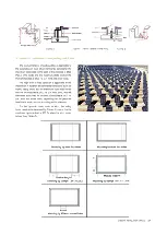
Page 8: ...ecialized clamps as shown in Figure 3 A Modules should be attached on a supporting structure rail by metal clamps lt is recommended to use the clamps under the following condition or approved by syste...
Page 9: ...onditions such as storm heavy snow etc the maximum static load on the back of the modules is 2400 Pa i e wind load and the maximum static load on the front of modules is 5400 Pa i e wind and snow load...
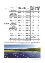
Page 10: ...s JAM72S03 PR 2400 N A 5400 2400 1800 2400 JAP72S03 se Series JAM72S09 PR 2400 N A 5400 2400 1800 2400 JAP72S09 se Series JAM72S10 PR JAP72S10 2400 N A 5400 2400 1800 2400 Se JAM72S10 MR Series JAM78S...
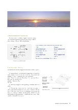
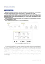
Page 11: ...lng and Parallel wlrlng W Diodes SI Over urrent ca Connector protactlon dev1ces Figure 5 Electrical diagrams of series and parallel wiring The maximum numberof Modulesthat can be connected in aseries...
Page 12: ...omply wlth local laws and rwgulatlons 3 Connectors Kaep connectors dryand clean and ensure lhatconnactorcaps are hand tlght before connectlng tha Modul811 Donot tmaldng an elec trical cor111action wit...
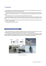
Page 13: ...otenlial difference of 0 6 Volts The frame rails have pre drilled holes marked wilh a grounding sign These holes should be used for grounding purposes and should not be used for mounling the Modules T...
Page 14: ...may reduce the power output and may even cause regional hot spot effect Industrial effluents or bird drops may be a serious case and the extent of the severity depends on the transparency of the forei...
Page 15: ...996x40 1979x996x35 1979x996x40 1979x996x35 1988x1005x40 JAP60S09 XXX SC 1657x996x35 1657x996x35 1666x1005x35 JAP72S09 XXX SC 1979x996x4Q 1979x996x35 1979x996x40 1979x996x35 1988x1005x40 JAM60S10 XXX P...