Jabiru Aircraft
Pty Ptd
Aircraft Service Manual
Jabiru J230-C
REVISION
0
Dated : Feb 2006
Issued By: RAS
Page: 11 of 171
L:\files\Technical_manuals\J230_J430\J230.J430_Work_files\J230-C_Tech_Rev_1.doc
Print Date: 14/01/2009 4:41:00 PM
1.1
TABLE OF FIGURES
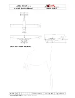
Figure 1. J230-C General Arrangement ...........................................................................................................16
Figure 2: Weighing Diagram.............................................................................................................................24
Figure 3. Fuel Line Routing..............................................................................................................................30
Figure 3. Undercarriage....................................................................................................................................32
Figure 4. Front Door Assembly.........................................................................................................................39
Figure 5: Rear Door Assembly .........................................................................................................................40
Figure 6. Door Latch Mechanism Assembly.....................................................................................................42
Figure 7. J230 Wing Assembly Sheet 1............................................................................................................47
Figure 8. J230 Wing Assembly Sheet 2............................................................................................................48
Figure 9 – Dynon Pitot Probe Installation .........................................................................................................50
Figure 10 – Landing Light Assembly.................................................................................................................51
Figure 11. Main Undercarriage Assembly ........................................................................................................55
Figure 12. Main Wheel Alignment.....................................................................................................................59
Figure 13. Main Wheel to Leg Assy..................................................................................................................60
Figure 14. Main Wheel Assembly.....................................................................................................................61
Figure 15. Directional Brake Disc Installation ...................................................................................................62
Figure 16. Nose Leg Assy.................................................................................................................................66
Figure 17. Nose Wheel Hub Assembly.............................................................................................................67
Figure 18. Brake Calliper Assy .........................................................................................................................73
Figure 19. Brake Master Cylinder Assy ............................................................................................................74
Figure 20. Aileron System Schematic...............................................................................................................76
Figure 21. Control Column Assy.......................................................................................................................78
Figure 22. Aileron Stops ...................................................................................................................................81
Figure 23. Flap Controls – Sheet 1 ...................................................................................................................85
Figure 24. Flap Controls – Sheet 2 ...................................................................................................................86
Figure 25. Flap Cross Tube Assy .....................................................................................................................87
Figure 26. Flap Position Indicator .....................................................................................................................88
Figure 27. Flap Position Indicator Drive Cable Assembly.................................................................................89
Figure 28. Elevator Control Assy ......................................................................................................................92
Figure 29: Elevator Control Assy Rear. ............................................................................................................93
Figure 30. J230 Models - Horizontal Tail & Elevator Assy................................................................................94
Figure 31. J170 Models - Horizontal Tail & Elevator Assy................................................................................95
Figure 32. Elevator Travel Limits ......................................................................................................................96
Figure 33. Elevator Trim Handle Assy ..............................................................................................................98
Figure 34. Trim Controls – At Tail.....................................................................................................................99
Figure 35. Rudder Pedal Assy ........................................................................................................................101
Figure 36. Rudder System Schematic ............................................................................................................104
Figure 37. Rudder Installation.........................................................................................................................105
Figure 38. Upper Cowl Assy ...........................................................................................................................107
Figure 39. Lower Cowl Assy ...........................................................................................................................108
Figure 40. LSA Variant Throttle (Panel Mounted)...........................................................................................113
Figure 41 – Instrument Panel & Throttle Assembly ........................................................................................114
Figure 42. Carburetor Heat Box......................................................................................................................115
Figure 43. Exhaust System.............................................................................................................................117
Figure 44. Engine Installation .........................................................................................................................119
Figure 45. Fuel System Schematic – LSA Variants........................................................................................121
Figure 46. Vented Fuel Cap Assy ...................................................................................................................125
Figure 47. Single Line Fuel Tap......................................................................................................................127
Figure 48. Fuel Gauge – Electric Sender Installation .....................................................................................128
Figure 49. Fuel Gauge – Electric Sender Assembly.......................................................................................129
Figure 50. Fuel Gauge – Sight Glass .............................................................................................................129
Figure 51. Header Tank Low Level Sensor Installation ..................................................................................130
Figure 52. Instrument Panel Layout (Std Panel).............................................................................................133
Figure 53. Instrument Panel Layout – “Glass” Instrument Panel....................................................................134
Figure 54. Pitot-Statice System – Water Trap Locations................................................................................140
Figure 55. Pitot Assembly – Std Pitot .............................................................................................................141
Figure 56. Static Probe System Assembly......................................................................................................142
Figure 57. Static System Test.........................................................................................................................143


