Jabiru Aircraft
Pty Ptd
Aircraft Service Manual
Jabiru J230-C
REVISION
0
Dated : Feb 2006
Issued By: RAS
Page: 112 of 171
L:\files\Technical_manuals\J230_J430\J230.J430_Work_files\J230-C_Tech_Rev_1.doc
Print Date: 14/01/2009 4:41:00 PM
11.5.2
LSA AIRCRAFT FUEL SYSTEM
1.
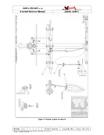
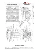
A schematic drawing of the system is shown as Figure 46
2.
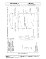
The fuel filter and auxiliary electronic fuel pump are mounted inside the header tank
enclosure.
3.
The low fuel pressure switch is located in the fuel line between the mechanical
engine fuel pump and the carbuettor.
4.
All fuel lines inside the cabin are housed within plastic sheath. This sheathing must
be maintained in good condition.
5.
The main fuel valve is located on the Main Beam in the cabin.
11.6 SPARK PLUGS
Refer to Engine Instruction & Maintenance Manual
11.7 ENGINE CONTROLS
11.7.1
RIGGING
When adjusting any engine control, it is important to check that the control slides smoothly
throughout its full range of travel & that the lever or knob moves through its full range of
travel.
11.7.2
THROTTLE SYSTEM
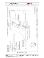
The throttle system used is shown in Figure 41. Note that the same system is used
irrespective of the instrument panel option fitted. Figure 42 shows the system fitted inside
the Glass instrument panel.


