Jabiru Aircraft
Pty Ptd
Aircraft Service Manual
Jabiru J230-C
REVISION
0
Dated : Feb 2006
Issued By: RAS
Page: 83 of 171
L:\files\Technical_manuals\J230_J430\J230.J430_Work_files\J230-C_Tech_Rev_1.doc
Print Date: 14/01/2009 4:41:00 PM
8.1.7
FLAP POSITION INDICATOR REMOVAL
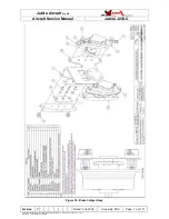
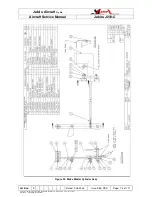
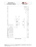
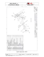
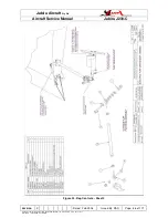
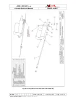
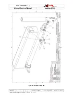
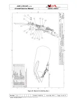
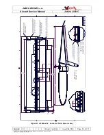
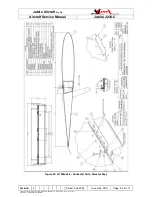
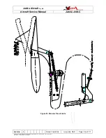
Refer to Figures 27 and 28 for guidance.
1.
Undo screws holding indicator to “A” pillar.
2.
Drill rivets and disassemble indicator.
3.
Loosen bolt on flap drive motor shaft & remove cable.
8.1.8
FLAP POSITION INDICATOR INSPECTION & REPAIR
Repair of the position indicator is limited to replacing worn or damaged parts.
8.1.9
FLAP POSITION INDICATOR INSTALLATION
Installation procedure is the reverse of the removal procedure outlined above.
8.1.10
FLAP CONTROL ROD
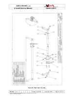
To remove, unbolt at both ends and remove. Reverse for installation.
8.2
FLAP
The flaps comprise a moulded and bonded monocoque structure embodying a composite
control arm at the inboard end.
8.2.1
REMOVAL AND INSTALLATION
1.
Unbolt rod end from flap control arm.
2.
Remove each flap hinge bolt and spacer.
3.
Remove Flap.
4.
Reverse the preceding steps for installation. Replace all three nyloc nuts and
torque in accordance with Table 2.
8.2.2
INSPECTION AND REPAIR
Inspect flaps for any signs of delamination or cracking. Pay particular attention to the
Control Horn and hinges and their surrounding areas.
Repairs must be referred to JABIRU AIRCRAFT Pty Ltd or our approved local agent.
8.2.3
FLAP BALANCING
The flaps on the J230 are not balanced.
8.2.4
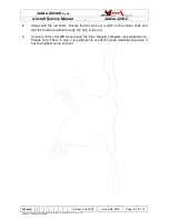
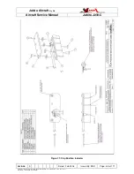
FLAP RIGGING (AS PER TEMPLATE)
1.
With the flap selector lever in the neutral position, use a straight edge not less than
1 metre long. Hold the straight edge flush on the underside of the wing aerofoil and
adjust flap so that the trailing edge of the flap sits on the straight edge and there is
4mm clearance between straight edge and trailing edge of the wing.

