Jabiru Aircraft
Pty Ptd
Aircraft Service Manual
Jabiru J230-C
REVISION
0
Dated : Feb 2006
Issued By: RAS
Page: 90 of 171
L:\files\Technical_manuals\J230_J430\J230.J430_Work_files\J230-C_Tech_Rev_1.doc
Print Date: 14/01/2009 4:41:00 PM
9
SECTION 9 – ELEVATOR CONTROL SYSTEM
9.1
ELEVATOR CONTROL SYSTEM
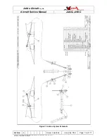
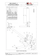
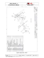
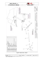
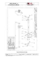
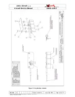
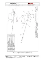
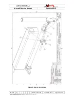
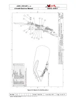
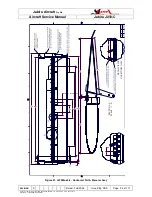
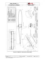
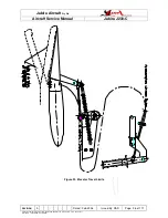
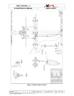
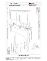
See Figures 29, 31 and Figure 32.
The elevator control system is comprised of a control column and one enclosed push-pull
cable fitted with rod ends at both ends.
WARNING
All spherical bearings must be fitted with a large washer on the outside of the
through-bolt to prevent the bearing case and cable releasing in the event of a
bearing failure.
9.2
CONTROL COLUMN DESCRIPTION
Refer to Figure 22.
9.2.1
REMOVAL AND INSTALLATION
Refer to Paragraph 7.2.1.
9.3
ELEVATOR
The elevator comprises a Rigid Cellular Polystyrene core moulded and bonded to a
composite skin and embodying a composite control horn at the centre. An elevator trim
system is attached – Refer Paragraph 9.6.
9.3.1
REMOVAL AND INSTALLATION
1.
Unbolt cable from control horn.
2.
Unbolt trim linkage from control horn.
3.
Loosen screws in hinge pin retainers and lift hinge pin retainers from hinge pins. It
is not necessary to remove these parts.
4.
Remove hinge pins.
5.
Remove Elevator.
6.
Reverse the preceding steps for installation.
9.3.2
ELEVATOR BALANCING
The J230 Elevator is balanced during construction. A standard weight of 750 grams of
lead is placed in each control horn to balance the elevator. In service there should be no
reason to rebalance the elevator. Balance may be checked with the control fitted to the
aircraft & the control & trim removed. Measure the force at the trailing edge required to
keep the elevator level. Weight & hinge moment values are given below:

