JABLOTRON FUTURA
SYSTEM DESIGN GUIDE
Page 9/16
JABLOTRON LIVING TECHNOLOGY
2
2 .. 7
7 .
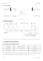
. VAC sch em e
VAC sch em e
Figure 6: VAC scheme
3
3 .
. Wiring diagram
Wiring diagram
Figure 7: Wiring diagram of 1-3 control panels, 0-8 CO
2
sensors, outdoor temperature NTC sensor, boost buttons and programmable inputs
4
4.
. Installation requirements
Installation requirements
4
4 .. 1
1 .
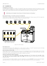
. Con n ect ion of ven t ila t ion p ip es
Con n ect ion of ven t ila t ion p ip es
OA - Outdoor air
∅
150 inner /
∅
210 outer
EPP pipes
EA - Exhaust air
∅
150 inner /
∅
210 outer
EPP pipes
SA - Supply air
∅
150
SONOCUT silencer
RA - Residual air
∅
150
SONOCUT silencer
The air inlet and outlet openings must remain free and clear! It is necessary to install silencers at the air supply and exhaust in the length of
approx. 1.5 m (5 ft). Note: It is necessary to leave 10 mm (0.4") gap under the door in all rooms with ventilation.


