JABLOTRON FUTURA
INSTALLATION MANUAL
37/43
JABLOTRON LIVING TECHNOLOGY
14
14 .. 8
8 .
. An n ex 8 - Room -b y -room ven t ila t ion (z on in g sy st em ) - D IP set t in g
An n ex 8 - Room -b y -room ven t ila t ion (z on in g sy st em ) - D IP set t in g
com b in a t ion s
com b in a t ion s
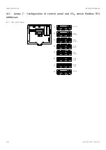
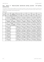
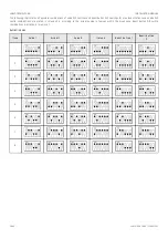
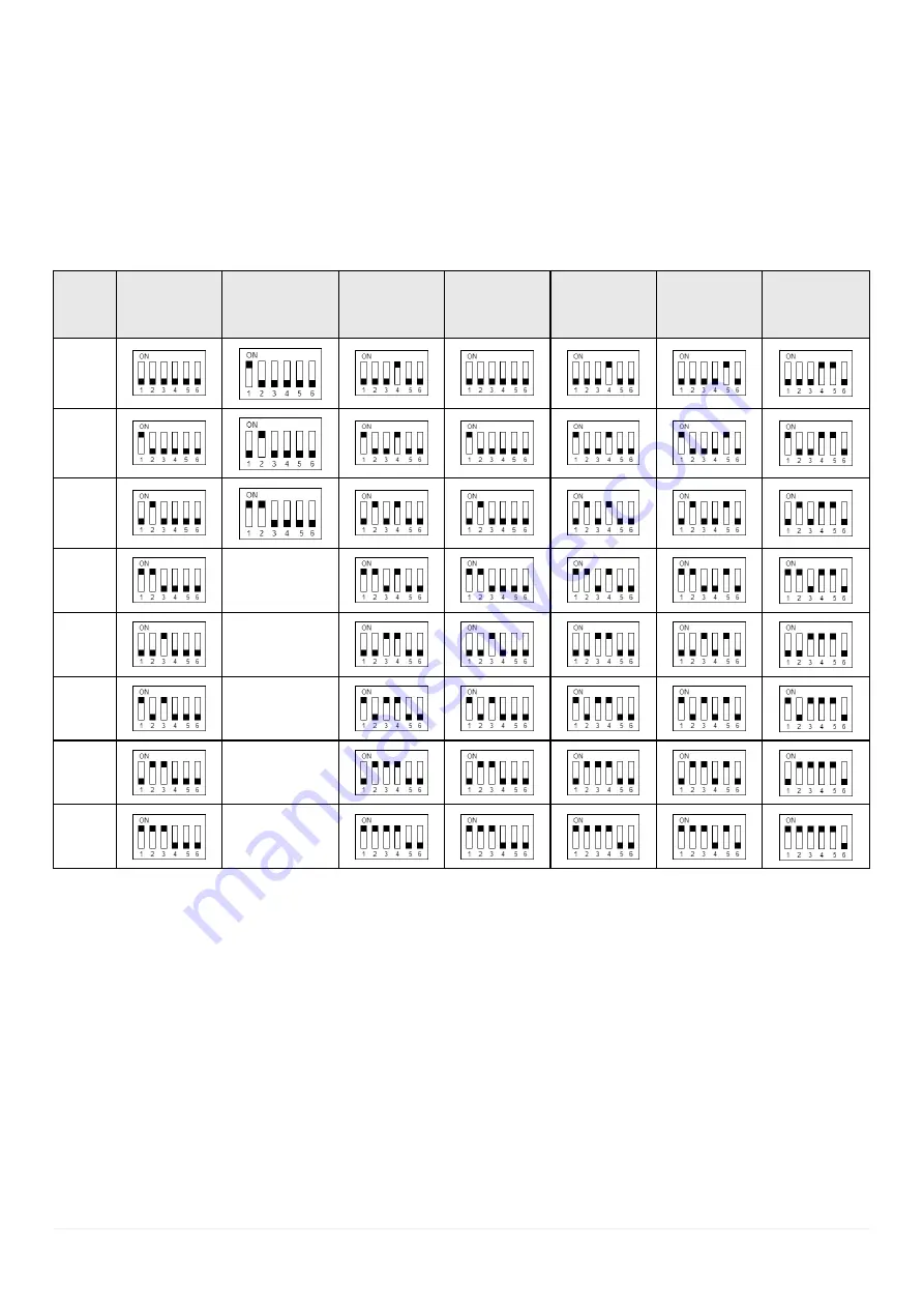
The following chart states all possible combinations of control panel DIP switches, CO
2
sensor DIP switches and valve DIP switches for max. 8
ventilation zones. Control panel and CO
2
DIP switch combinations are stated in columns 2-4. Valve DIP switch settings are stated in columns 5-8
according to the actual number of valves within the given zone.
S u p p l y z o n e s
S u p p l y z o n e s
Z on e
Z on e
A lfa
A lfa
W a ll-
W a ll-
mou n t ed
mou n t ed
con t rol p a n el
con t rol p a n el
C O
C O
2
2
s en s or
s en s or
V a lv e 1
V a lv e 1
V a lv e 2
V a lv e 2
V a lv e 3
V a lv e 3
V a lv e 4
V a lv e 4
1
2
3
4
---
5
---
6
---
7
---
8
---


