Alarm system JA-65 MAESTRO
- 6 -
MFM53003
1,2,3,4
- digital data terminals (see K4, K6) provide an option to
use standard cable for the wiring of JA-60E keypads. The
keypads are also equipped with both jacks and terminals.
The following terminals are on the bottom side of the
main board:
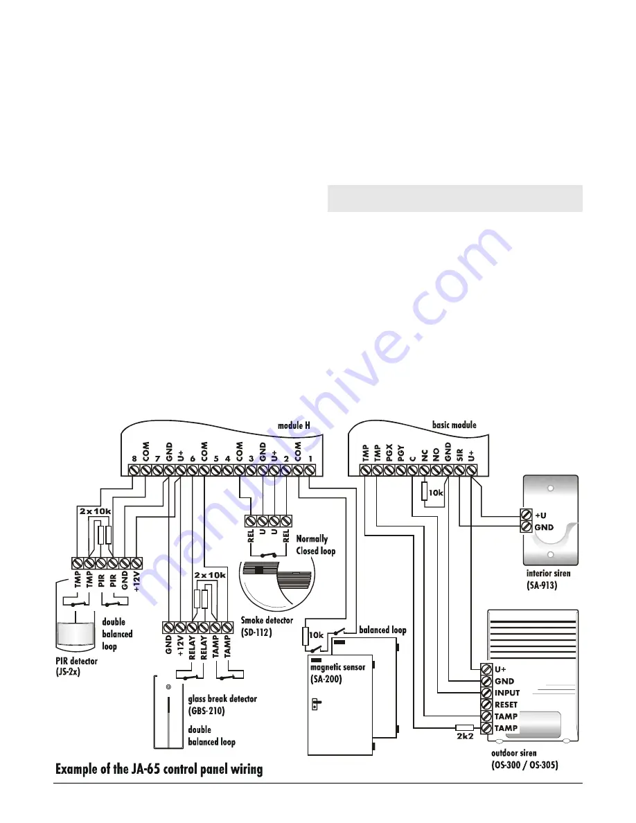
TMP
a pair of terminals to connect the tamper switch of an
external device (for example: a wire operated outdoor
siren, OS-300). In normal use, these terminals should be
connected together via a 2k2 resistor. Triggering of this
loop has the same effect as control panel tampering (a
change of ±30% or more of the End Of Line resistor will
trigger the input).
PGX
is an output (transistor switching to GND, max. 12V,
100mA). The function of this output is determined by the
setting in the programming mode (see 11.6). The control
panel also wirelessly transmits the PGX signal and unit
UC-216 or UC-222 can be used as a remote output of this
signal.
PGY
is an output (transistor switching to GND, max. 12V,
100mA). The function of this output is determined by the
setting in the programming mode (see 11.6). The control
panel also wirelessly transmits the PGY signal and unit
UC-216 can be used as a remote output of this signal.
C
is a common contact of the alarm output relay, max. load
60V / 1A. The relay is turned on during any alarm of the
control panel.
NC
is a normally closed contact of the alarm output relay.
NO
is a normally open contact of the alarm output relay.
GND
is a common ground terminal of the power output (-). This
terminal is also available on 65H modules.
SIR
is an external siren output. In the normal mode it has the
+U terminal voltage. In the alarm mode it has a GND
terminal potential. Connect an ordinary external siren to
+U and SIR terminals (max. load 0,7 A). A back up siren
charging input should be connected to the GND and the
SIR terminals (during an alarm, the charging will
temporarily halt). The siren can also be used for sounding
arming and disarming chirps and as an audible indicator
while in the testing mode.
+U
is a back up power output for external items (detectors
etc.). The max. permanent current is 0.7 or 1.2 A for max.
15 min (not more then one cycle per hour). This output is
fused and supervised by the control panel. If it is
overloaded, a control panel failure will be indicated (fault
C). The muU terminals are also available on the JA-
65H hard-wire modules for easier wiring. All +U terminals
are connected in parallel to the +U terminal of the main
board.
6. The JA-65H hard wired input module
terminals
Up to two 65H modules can be used in the control panel. The
module with its cable connected directly to the main board
provides zone inputs 1 to 8. If the second module is installed it
will provide zone inputs 9 to 16. The 65H module has the
following terminals:
1 to 8
zone inputs
– Normally, detector outputs are wired here:
see examples of wiring in diagram. For each input it is
possible to program its method of triggering: Normally
Closed loop, balanced
loop (10k
)
or double balanced
loop (2x 10k) and the type of reaction of the system
(see section 11.2).
COM
Four common terminals to close (balance) the input
loops
GND
ground (negative pole) of the power supplier
+U
backup power output for external devices (detectors etc.),
max. total consumption form all +U terminals in the control
panel can be 0,7 A.
Summary of Contents for MAESTRO JA-65
Page 1: ...JA 65 MAESTRO Alarm system installation manual...
Page 2: ......


