4
WASTE PUMP SERVICE
The Jabsco Quiet-Flush Toilet does not require routine
maintenance other than occasional cleaning to maintain
a hygienic sanitary condition. Clean toilet with mild
non-abrasive cleaners without strong aromatics. Clean-
ers having high concentrations of aromatics such as
pine scented concentrated cleaners and strongly scent-
ed degreaser concentrates can cause the pump’s seal to
swell and may contribute to a premature seal leak.
The toilet has no wearing parts that need periodic
replacement other than the shaft seal which, under nor-
mal conditions, should provide several years of service
before needing replacement. The seal only requires
replacement if signs of leakage are noticed under the
seal housing positioned between the motor and toilet
base assembly.
NOTICE: Before performing any service, turn off the
electrical power to the toilet and rinse water pump. Take
precaution to ensure it is not turned on until the service
is complete. Also, pump all water from the toilet bowl and
if connected to an overboard discharge, close the dis-
charge seacock.
To replace the shaft seal, snap off the white motor cover
and remove the pump assembly by removing the four
screws with lock washers that secure it to the toilet base.
Carefully slide the pump assembly from the base ensuring
the macerator housing also slides out of the base with the
pump. The pump chopper will engage the macerator hous-
ing and it may be necessary to gently tap the chopper
against the macerator housing to free it from the base.
Prevent the motor shaft from turning by inserting a
screwdriver in the shaft slot at the rear of the motor and
unscrew the nut. Remove the chopper blade and mac-
erator housing from the motor shaft. Remove the O-ring
from the O-ring groove around the outer diameter of the
seal housing. With an allen wrench, loosen the centrifu-
gal impeller set screw and slide the impeller off the shaft.
Remove the two screws that secure the seal housing to
the motor and slide the housing off the motor shaft.
Remove the two seal washers from under the head of
each of the two seal housing retainer screws. With a pair
of needle nose pliers, grasp the shaft seal and pull it
from the seal housing. Clean all parts and inspect for
damage.
Lubricate the OD of the new seal with a small amount of
water and press it into the seal bore with the seal’s lip
facing the threaded end of the shaft. Do not use the
stainless steel star retaining washer supplied with the
seal. Lubricate the ID of the seal and the motor shaft
with a small amount of water resistant grease. Ensure
the slinger is properly positioned on the motor shaft next
to the motor and slide the seal housing onto the motor
shaft until it is against the motor end bell. Position a new
plastic seal washer under the head of each of the flat
head seal housing retainer screws and secure the seal
housing to the motor. Slide the centrifugal impeller on
the motor shaft positioning it about 1/32
" (1 mm) from
the seal housing and secure it to the shaft with the set
screw. Rotate the impeller to ensure it does not rub on
the seal housing.
Slide the macerator housing over the motor shaft, place
the chopper plate on the end of the shaft and screw the
locking nut onto the shaft. Tighten the nut while holding
the motor shaft at the rear of the motor. Position a new
O-ring in the seal housing O-ring groove (it may be
retained in the groove with a small amount of grease).
Slide the pump assembly into the toilet base ensuring
the macerator housing is properly positioned within the
base. The cut-out in the side of the macerator housing
must align with the discharge port in the base (the
macerator housing is keyed so it will only go in when
properly positioned). Ensuring the O-ring is still properly
positioned in the O-ring groove in the seal housing,
place the pump assembly against the base and secure it
in place with the four screws and lock washers. Replace
the white motor cover by snapping it down over the
pump motor.
PAR-MAX 2.9 Rinse Pump Service
Please refer to the Data Sheet provided for
the 31331-Series Rinse pump.
Flood hazard. If toilet is plumbed to an
overboard discharge, close the discharge
seacock prior to disassembling toilet.
Failure to do so can result in flooding which
can cause loss of property and life.
WARNING
!
8
9
7B
10
11
14
12
13
20
4
15
16 17
18
19
21 22
23 24
25
26
1
3
2
7A
7B
7C
7D
7F
29
7E
5
6
FLUSH
FILL
DRAIN
27
28
27a
27
5
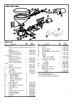
PARTS LIST
Qty.
Part
Key
Description
Req.
Number
1. Seat & Cover
Note - 2018 models identified with Jabsco logo on top
of bowl.
Compact 1 29097-1000
Regular (Pre 2018) 1 29127-1000
Regular (2018 onwards) 1 58104-1000
Soft Close (2018 onwards) 1 58104-2000
1a. Hinge Sets
Hinge Set (1 PAIR)
Compact (ALL VARIANT) 1 29098-1000
Regular (Pre 2018) 1 29098-2000
Regular (2018 onwards) 1 58105-1000
Soft Close (2018 onwards) 1 58105-2000
2. Bowl
Compact 1 29096-1000
Regular
1 29126-1000
3 & 4
Bowl Spud, Intake Elbow
1
29048-0000
& O-ring
1
3
0
1
-
5
3
0
9
2
1
t
e
e
f
6
,
e
s
o
H
5
6
Motor Cover †
1
37042-1000
7
Bowl Installation Hardware
1
18753-0637
7A
Hex Head Screw**
4
7B
Washer, Starlock**
4
7C
Washer, Plastic**
4
7D
Washer, Stainless Steel**
4
7E
Hex Nut** (Two places)
8
4
*
*
p
a
C
t
u
N
F
7
8
Bowl O-Ring Seal
1
44101-1000
9
Base Assembly**
1
37004-1000
10
1-1/2
" Adaptor, Discharge Port
1
98023-0080
11
Joker Valve* **
1
44106-1000
12
1
" Discharge Port**
1
44107-1000
8
6
5
0
-
0
5
0
6
9
3
*
*
w
e
r
c
S
3
1
14
Chopper Plate with Lock Nut †
1
37056-1000
15
Macerator Housing †
1
37014-0000
16
Centrifugal Impeller †
1
37006-0000
2
9
4
0
-
3
5
7
8
1
1
†
w
e
r
c
S
t
e
S
7
1
6
6
0
0
-
0
9
9
3
4
1
†
*
g
n
ir
-
O
8
1
Qty.
Part
Key
Description
Req.
Number
0
0
0
0
-
0
4
0
1
1
†
*
l
a
e
S
9
1
4
4
1
0
-
0
1
0
1
9
2
†
w
e
r
c
S
0
2
21
Washer, Plastic* †
2
35445-0000
22
Seal Housing †
1
37043-1000
23
Lock Washer #10, Stainless Steel† 4
1
1
0
0
-
7
2
0
1
9
4
†
w
e
r
c
S
4
2
0
0
0
0
-
2
4
3
6
1
†
r
e
g
n
il
S
5
2
26
Motors:
Motor - 12 Volt EMC †
1
18753-0554
Motor - 24 Volt EMC †
1
18753-0555
27
PAR-MAX 2.9 Rinse Pump
12 Volt
1 31331-0092
24 Volt
1 31331-0094
27a Pump Guard
1 46400-9500
28
Switch Panel
1
37047-1000
29
Screw Cover (3 each)
1
37003-1000
0
0
0
0
-
7
9
1
0
9
ti
K
e
ci
v
r
e
S
Waste Pump Assembly
2
9
0
0
-
2
7
0
7
3
t
l
o
V
2
1
4
9
0
0
-
2
7
0
7
3
t
l
o
V
4
2
* Parts Supplied with Service Kit.
** Parts included with base 37004-1000.
† Parts included in Waste Pump Assembly
EXPLODED VIEW
Summary of Contents for 37245-3092
Page 7: ...NOTE ...


