background image

3

ELECTRICAL

The electrical wiring should be independent of all other 
accessories. It should be made with marine grade copper
stranded wire of the gauge specified in the electrical 
specifications chart. Make all wire connections with 
mechanical locking type connectors (crimp type butt 
connectors and terminals). Ensure the circuit is protected
by a proper sized fuse or circuit breaker determined from
the electrical specifications chart. Secure all wires to a
solid surface approximately every eighteen inches (1/2 M)
along their entire length of run.

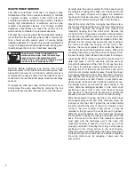
Wire the switch panel to the PAR-MAX rinse pump and 
toilet waste pump as per the following wiring diagram. The
brown lead from the control panel connects with the waste
pump orange (positive) motor lead. The yellow lead from
the control panel connects with the PAR-MAX rinse water
pump orange (positive) motor lead. The black motor lead
from each pump must be connected to battery negative.
Select a location for the switch panel that is convenient to
the toilet user and will also allow access to run the wires
from the switch panel to both the toilet’s waste pump motor
and the PAR-MAX pump as well as from the electrical
power source to the switch panel. To install the switch
panel, drill two 1-3/4

" (45 mm) diameter holes (slightly

over-lapping) through the selected switch mounting 
surface per the attached template. Ensure the template is
oriented correctly because it is not symmetrical. Also,
drill four appropriate sized holes for the fasteners selected
to secure the switch panel to its mounting surface.

WIRING DIAGRAM

RED

BROWN YELLOW

BROWN

YELLOW

RED

RED

RED

BROWN

YELLOW

UP

1-3/4" (45 mm) DIA

1-3/4" (45 mm) DIA

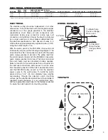
ELECTRICAL SPECIFICATIONS

AMP

FUSE

WIRE SIZE PER FEET OF RUN*

VOLTAGE

DRAW

SIZE

0'-10' (0 M-3 M)

10'-15'(3 M-4.6 M)

15'-25'(4.6 M-7.6 M)

25'-40'(7.6 M-12.2 M)

40'-60'(12.2 M-18.3 M)

12 Vdc 

10

25

#16 (1.5 mm

2

)

#14 (2.5 mm

2

)

#12 (4 mm

2

)

#10 (6 mm

2

)

#8 (10 mm

2

)

24 Vdc

5

15

#16 (1.5 mm

2

)

#16 (1.5 mm

2

)

#16 (1.5 mm

2

)

#14 (2.5 mm

2

)

#12 (4 mm

2

)

* Length of run is total distance from power source to product and back to ground.

To PAR-MAX
Pump Positive
(Orange) Motor
Lead

To Waste Pump
Positive (Orange)
Motor Lead

To Positive

TEMPLATE

Summary of Contents for 37245 Series

Page 1: ... 24 Volt DC 37245 0094 Compact Size Bowl 24 Volt EMC 37245 1012 Household Size Bowl 12 Volt DC 37245 1092 Household Size Bowl 12 Volt EMC 37245 1024 Household Size Bowl 24 Volt DC 37245 1094 Household Size Bowl 24 Volt EMC This model is Marked and complies with EN50081 1 for suppression of electro magnetic interference OPERATION The Quiet Flush toilet provides both quiet operation and user control...

Page 2: ...llapse or kink Route the inlet hose from a 3 4 19 mm through hull and seacock fit ting located well below the waterline and well forward of any discharge through hulls if installed to the pump inlet port Ensure the inlet hose passes through an accessible location preferably above the vessel s waterline that will allow for the installation of the Toilet Pumpgard strainer where it can be periodicall...

Page 3: ...panel that is convenient to the toilet user and will also allow access to run the wires from the switch panel to both the toilet s waste pump motor and the PAR MAX pump as well as from the electrical power source to the switch panel To install the switch panel drill two 1 3 4 45 mm diameter holes slightly over lapping through the selected switch mounting surface per the attached template Ensure th...

Page 4: ...ousing off the motor shaft Remove the two seal washers from under the head of each of the two seal housing retainer screws With a pair of needle nose pliers grasp the shaft seal and pull it from the seal housing Clean all parts and inspect for damage Lubricate the OD of the new seal with a small amount of water and press it into the seal bore with the seal s lip facing the threaded end of the shaf...

Page 5: ...ing 1 37014 0000 16 Centrifugal Impeller 1 37006 0000 17 Set Screw 1 18753 0492 18 O ring 1 43990 0066 Qty Part Key Description Req Number 19 Seal 1 1040 0000 20 Screw 2 91010 0144 21 Washer Plastic 2 35445 0000 22 Seal Housing 1 37043 1000 23 Lock Washer 10 Stainless Steel 4 24 Screw 4 91027 0011 25 Slinger 1 6342 0000 26 Motors Motor 12 Volt 1 18753 0554 Motor 12 Volt EMC 1 18753 0582 Motor 24 V...

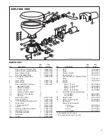
Page 6: ...rt retainer clip forward until it snaps securely into its seated position Reconnect the orange motor lead to the positive supply wire and the black motor lead to the negative wire Ensure the inlet seacock is open before restoring power to and operating the toilet EXPLODED VIEW PARTS LIST Qty Part Key Description Req Number 1 Port Kit 1 pair 1 30653 1004 2 Body Kit 1 30608 1001 3 Valve Cage Valve A...

Page 7: ...herein and applies only for the period designated above 2 JABSCO SHALL NOT BE LIABLE FOR ANY LOSS DAMAGE SPECIAL OR CONSEQUENTIAL DAMAGE OF ANY KIND WHETHER BASED UPON WARRANTY CONTRACT NEGLIGENCE OR STRICT LIABILITY ARISING IN CONNECTION WITH THE SALE USE OR REPAIR OF THE PRODUCT 3 THE MAXIMUM LIABILITY OF JABSCO IN CONNECTION WITH THIS WARRANTY SHALL NOT IN ANY CASE EXCEED THE CONTRACT PRICE FOR...

Page 8: ...s Printed in U S A All Rights Reserved Form 43000 0662 Rev 2 2003 THE PRODUCTS DESCRIBED HEREIN ARE SUBJECT TO THE JABSCO ONE YEAR LIMITED WARRANTY WHICH IS AVAILABLE FOR YOUR INSPECTION UPON REQUEST 1 Dia 25 4 102 6 152 6 5 8 168 8 1 8 206 C Overall Width B F D E 5 16 8 3 1 8 79 A 9 229 12 3 8 314 3 1 4 83 5 3 4 146 2 Leads 11 Long 279 DIMENSIONAL DRAWING INCHES MILLIMETRES A B C D E F Compact Si...

Reviews: