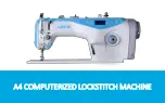
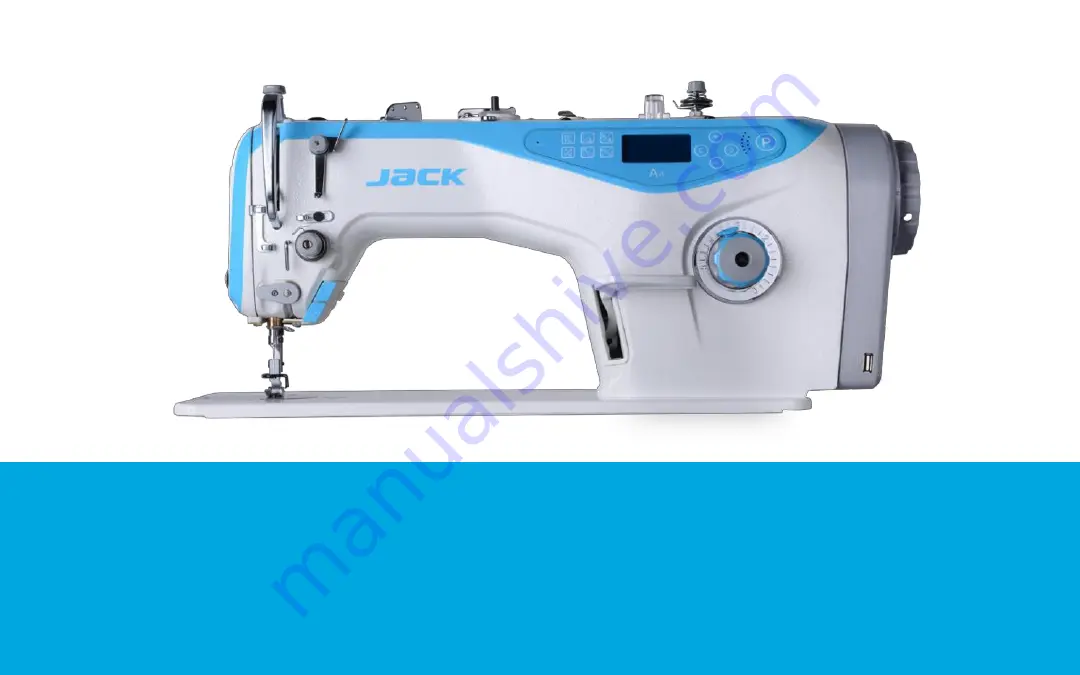
background image


A4 COMPUTERIZED LOCKSTITCH MACHINE 

Summary of Contents for A4

Page 1: ...A4 COMPUTERIZED LOCKSTITCH MACHINE...

Page 2: ...Product introduction A A3 A4 A4S Followed by A2 A2S A5 A6 etc...

Page 3: ...Product introduction A Each operation has voice guide Each botton has voice reminder USB Port For charging cell phone PROJECT NAME date CONFIDENTIA L 3 Voice Reminder Little reminder big sweetness...

Page 4: ...button Operation steps On the condition of power on using a sharp objective PROJECT NAME date CONFIDENTIA L 4 insert into the hole for 3 seconds to restore the factory default When the screen shows t...

Page 5: ...02operating instructions before and after backstitch operating steps In standby mode press key Set the number of before and after backstitch number of after backstitch number of before backstitch...

Page 6: ...tch LED screen area PROJECT NAME date 6 Free sewing Press the button and the icon display means it s free sewing mode at present Trimming switch Press the button longer the icon display up means the t...

Page 7: ...ate CONFIDENTIA L 7 A B refers to the stitch numbers of initial and final sewing D refers to sewing times W sewing Press the button and the icon Press the button to the corresponding number flicking t...

Page 8: ...e the section number when you adjust The stitch number setting the first segment of the stitch number is 16 and the range of the stitch is from 1 to 99 LED screen area PROJECT NAME date CONFIDENTIAL 8...

Page 9: ...ing Press the button and the icon display on the LED screen means the tension device is on Press the button again the icon not display means the tension device is off Setting of presser foot lifter se...

Page 10: ...ing Press the icon display means that the press foot lifter after trimming is on Press again the icon not display means that the press foot lifter after trimming is off The midway press foot lifter se...

Page 11: ...face return to standby state Parameter Adjustable range System default Parameter description P 0 1 200 5000 3500 the maximum speed of free sewing the maximum speed P 0 3 0 1 1 Needle position selectio...

Page 12: ...pensation P 2 2 0 50 8 the interval of on and off gear when adding one stitch P 2 4 0 1024 80 Trimming point of pedal P 2 5 1 120 35 Stitch balance for end back tacking No 1 P 2 6 1 120 20 Stitch bala...

Page 13: ...output time ms P 5 1 1 100 3 Presser foot lifting electromagnet per cycle opening time ms P 5 2 0 800 100 Running delay time ms when presser footer comes down to the beginning of sewing A little more...

Page 14: ...off P 6 8 0 5000 4000 The upper limit of the maximum speed P 7 1 0 50 2 Slow release lifter level adjustment the smaller values and the faster quickly P 7 6 1 500 60 Back sewing electromagnet full out...

Page 15: ...e hours of motor 0 1 2 real speed of the head 0 2 8 The sampling voltage of interaction 0 1 3 State of encoder 0 2 9 DSP Software version 0 2 0 DC voltage 0 2 A Simulate inputing sampled value 1 0 2 1...

Page 16: ...r voltage when the machine is off Err 05 Over voltage in operation Err 06 Magnet circuit fault 1 Check whether the plug pin is fall off2 Unplug the electromagnet plug to see if is still in an error 3...

Page 17: ...1 Check the connection between control panel and controller 2 factory reset3 Replace the panel 4 Replace the electric cabinet Err 11 Machine head needle positioning failure 1 Check whether the plug i...

Page 18: ...15 Motor over speed protection Err 16 Motor reversion Err 17 HMI Read Write EEPROM failure Err 18 Motor overload Err 23 Sewing motor blocked encoder failure According to E08 to investigate solution i...

Page 19: ...Mechanical adjustment lower shaft oil supply srew of adjusting to the oil of hook oil pump pipe alumin um...

Page 20: ...e the wick Needle bar oil amount is too large adjust the position of the wick The installation of lubricato wick of Needle bar In the process of high speed machine needle bar in the move up and down t...

Page 21: ...ent oil return oil return pipe Mainly absorbed back the excess oil of the head to avoid oil to the workbench from the needle bar or press foot linoleum Absorb the excess oil supply then oil return pip...

Page 22: ...Mechanical adjustment Adjustment of the needle bar height Adjustment of the needle bar height When the needle in the lowest hook within half a pinhole...

Page 23: ...e the hook tip to the center needle and then continue to turn the handwheel to make the needle from down to up in 2 2 2 5 mm then to keep hook tip to above the pinhole between 1 1 2 mm and also the ho...

Page 24: ...ustment of Positioning hook Adjustment of Positioning hook The left to right of the positioning hook is generally about 0 5 1 0 mm The gap is too large the sound is loud the gap is too small crossed t...

Page 25: ...ew Feed dog tilt screw 1 When the needle pitch reaches the maximum by adjusting the feed dog before and after the screw make before and after the feed dog do not touch the needle plate 2 By adjusting...

Page 26: ...f the feed dog Pinhole bottom flush To get the synchronous adjustment of needle and the feed dog easy breakage when feed dog is too slow back stitch is more obvious When the feed dog is too quickly th...

Page 27: ...nical adjustment coincidence degree of the back stitch needle pitch Loosen the two retaining screws adjust the reverse stitching eccentric shaft make the back and forth stitch coincidence retaining sc...

Page 28: ...stallation function From top to bottom Pay off for the hook to hook thread when the hook turn to 180 degrees the take up lever take back the extra thread form stitch installation take up plane aim to...

Page 29: ...Mechanical adjustment Stitch adjustment method link Press the button on the lockstitch dial rotate to the left stitch becomes larger rotate to the right stitch becomes smaller...

Page 30: ...Mechanical adjustment trimming...

Page 31: ...stment method 1 Before we adjust the trimmer time must adjust the height of the needle bar the time when hook catch thread and the machine stop position 2 when the distance between hook distribution p...

Page 32: ...sented as ABCD in the picture 2 Take down the electronic control box and then use hex key 4mm to loose the screw represented as E in the lower left corner of the picture 3 Loose 6 motor encoder fasten...

Page 33: ...uncements 1 Rotating the first screw of the motor grating film to fix flat 2 After replacing the grating film need to make sure the left right position of the grating film and don t touch the encoder...

Reviews: