1/7
·
Please read this manual carefully, also with related manual for the machinery before use the
controller.
·
For installing and operating the controller properly and safely, qualified personnel are required.
·
Please try to stay away from arc welding equipment, in order to avoid electromagnetic interference
and malfunction of the controller.
·
Keep in room bellow 45°c and above 0°c
·
Do not use in humidity below 30% or above 95% or dew and mist of places.
·
Install the control box and other components, turn off the power and unplug the power cord.
·
To prevent interference or leakage accidents, please do the ground work; the power cord ground wire
must be securely connected to an effective way to earth..
·
All parts for the repair provided by the Company or approved before use.
·
Performing any maintenance action, you must turn off the power and unplug the power cord. There
are dangerous high voltage control box, you must turn the power off after one minute before opening
the control box.
·
This manual marked with the symbol of the Department of Safety Precautions must be aware of and
strictly adhered to, so as not to cause unnecessary damage.
Jack A4 Computer Integrated Machine Operation Manual
1 Installation Instructions
1.1 Product specifications
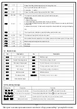
Product Type
AHE59
Supply Voltage
AC 220 ±
20%
V
Power frequency
50Hz/60Hz
Maximum output power
550W
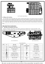
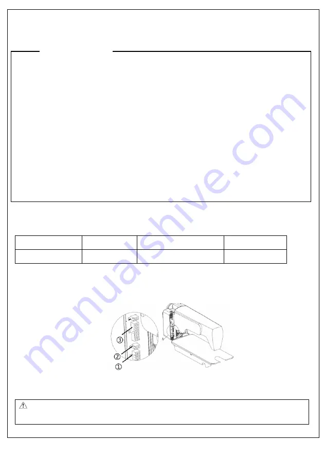
1.2 Interface plug connections
The pedals and the machine head of the connector plug are mounted to the corresponding position in the controller back of
socket, as shown in Figure 1-2. Please check if the plug is inserted firmly.
Fig.1-1 Controller Socket Diagram
①
Pedals socket;
②
Foot lifter solenoid socket ;
③
Machine head solenoid socket;
:
The use of the normal force are not inserted into the plug and socket, please check whether the matching, direction or
needle insertion direction is correct!
Safely Instruction
Интернет магазин промышленного швейного оборудования http://procapitalist.ru/sms