background image

C4 Training courseware 

Summary of Contents for C4

Page 1: ...C4 Training courseware...

Page 2: ...PRODUCTS INTRODUCTION OPERATION INSTRUCTIONS MAINTENANCE INSTRUCTIONS IMPROVED POINTS INTRODUCTION 01 02 03 04 CONTENT...

Page 3: ...PRODUCTS INTRODUCTION OPERATION INSTRUCTIONS MAINTENANCE INSTRUCTIONS IMPROVED POINTS INTRODUCTION 01 02 03 04...

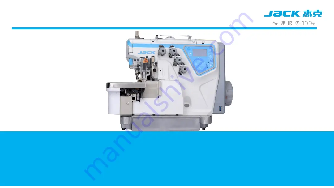
Page 4: ...900E but only use non shell hall servo motor integrated control box three proofing sensor needle bar avoiding oil leakage technology USB technology and several other new technology voice guide bigger...

Page 5: ...roduct introduction Type plate introduction Feed dog teeth space distance1 6mm Feed dog teeth column number Upper looper stroke6X6 Medium heavy material Normal seam for medium heavy material Thread nu...

Page 6: ...astest Automatic Overlock Machine Highest Speed 7000rpm min Max Length mm 0 8 4 8 Thread Wideth mm 1 5 8 0 Differential 0 7 2 0 Presser Foot Height mm 5 0 7 0 Needle Type DCX27 Needle Bar Height gener...

Page 7: ...5 5 7000 4 C4 3 32R2 223 pearl stitch 9 1 3 1 5 3 8 0 7 2 5 7000 5 C4 3 82 233 P pneumatic backstitch 11 1 3 4 3 8 0 7 2 5 7000 6 C4 4 83 323 P pneumatic backstitch 11 2 4 2 4 4 2 0 7 2 5 5 7000 7 C4...

Page 8: ...LOREM IPSUM DOLOR 8 Content Product introduction Operation instruction Maintenance instruction Improved point introduction 01 02 03 04...

Page 9: ...Improved point introduction New Outlook Design New Visual Hammer New Strip Technology...

Page 10: ...New Panel Easy to operate Integrated control box easy to use USB upgrade Improved point introduction...

Page 11: ...Improved point introduction The thread clamp device offset Needle bar suction nozzle To prevent the needle bar leak oil Inset LED light Good looking...

Page 12: ...Improved point introduction Three transmitters Independent presser foot wrench Easy operation The sensor cover wear prevention...

Page 13: ...Improved point introduction Built in compressive bar Higher precision Build in integrated box Good looking Presser foot push rod fork design Force uniform noise reduction...

Page 14: ...Improved point introduction The third piece of oil seal Oil leak prevention Thread take up radian evenly Collect thread more stable Hall without shell Servo motor...

Page 15: ...PRODUCTS INTRODUCTION OPERATION INSTRUCTIONS MAINTENANCE INSTRUCTIONS IMPROVED POINTS INTRODUCTION 01 02 03 04...

Page 16: ...roduction Integrated electric control box motor Large air volume finger print hand wheel USB Port Simple operation panel Embedded LED Separate emitter Anti sun dust abrasion sensor Tilt tension device...

Page 17: ...meter content area increase the parameter 4 Down Key 1 Decrease Speed2 parameter content area decrease the parameter 5 Right Key 1 Adjust LED brightness 2 parameter content area select the right side...

Page 18: ...5S no action is back to the standby interface In the corresponding mode to modify the maximum speed of P1 P3 starting speed P10 automatic presser foot lifter P17 semi intelligent continuous sewing P27...

Page 19: ...e continusly press this key switch the trimmer mode In cycles Pre cutting after cutting Pre After cutting Off Pre cutting length adjust Press Small value means long After cutting length Press to adjus...

Page 20: ...ode continually press this key switch the auto presser foot mode In cycles Pre lift after lift pre after lift Off press to save 5S no action is back to the standby interface parameter association When...

Page 21: ...d Adjustment IntroductionMOV In stand by mode press speed up one time increase by 100RPM press speed down one time decrease by 100RMP then press to save if no any press for 5S then it will be back to...

Page 22: ...for the screen brightness In stand by mode press continuously to adjust the screen brightness Now instead of Eight kinds of countries language for switching There are four levels for the LED brightnes...

Page 23: ...greeting voice and key pressing guide voice In stand by mode short press to turn on and off the greeting voice Long press to turn on and off the pressing guide voice When Error is there you can short...

Page 24: ...rameter reset user default parameter Users adjust the parameter according to his own habit and requirement After changing value of parameter 21 to 1 for backup press is for user default parameter rese...

Page 25: ...tion Instructions Key Lock AdjustmentMOV When you change the value of parameter 62 to 1 all the keys in the panel will be locked all the keys don t work Long press for 1 5s to unlock all the keys will...

Page 26: ...avoid cutting sensor delay stitches P50 defaults to 0 If the P50 item saves the parameter value change the P50 item parameter is equal to the user saves the parameter value When the avoid cutting sens...

Page 27: ...avoid cutting sensor delay stitches P50 defaults to 0 If the P50 item saves the parameter value change the P50 item parameter is equal to the user saves the parameter value When the avoid cutting sens...

Page 28: ...ctions the specific operation is as follows Under the standby mode press the P key the voice key Enter to environment automatic identification function after identify will automatically return Go back...

Page 29: ...troduction Actual value 0 1 2 3 4 5 6 7 8 9 Digital display English alphabet A B C D E F G H I J Digital display English alphabet K L M N O P Q R S T Digital display English alphabet U V W X Y Z Digit...

Page 30: ...de Adjustment by key key to modify the parameter adjustment items through the key key to adjust the corresponding parameters Numerical values The user parameter mode is from P26 P68 3 System parameter...

Page 31: ...RPM P2 Stop positioning selection 0 2 1 0 No positioning 1 up position 2 down position P3 Start speed 500 7000 5500 RPM P4 Start mode 0 1 0 0 Auto mode 1 foot control mode P5 Mode selection 0 2 1 0 F...

Page 32: ...for start and end trimmer 4 suction always on P9 Reverse press pedal trimmer switch 0 1 1 0 off 1 on P10 Auto presser foot lifter 0 3 0 0 off 1 start lift 2 end lift 3 start and end lift P11 presser...

Page 33: ...2 front and back suction P15 LED light switch 0 3 1 0 off 1 3 on P16 sleep mode switch 0 1 1 0 off 1 on P17 Semi auto continuous sewing 0 2 2 0 Off 1 Touch front pedal for continuous sewing 2 continuo...

Page 34: ...re version P21 User parameters commonly used 0 1 0 0 No operation 1 Save parameter for user commonly used P22 Front sensor switch 0 1 1 0 off 1 on P23 Front suction opening time 1 250 5 Front suction...

Page 35: ...ishing fabric sewing and no shield for the sensor P27 stitch delay for front trimming 0 10 2 Stitch number more thread short P28 Stitch delay for back trimming 0 50 8 Stitch number more thread short P...

Page 36: ...1 99 99 P35 Stitch delay for machine stopping 1 99 1 P36 Front sensor response time 5 50 10 10 ms Sensitivity P37 Front sensor sensitivity 20 40 36 Sensitivity is more higher its easy to identify the...

Page 37: ...foot giving power round signal 0 50 15 10 ms Opening time The round time is 5MS P43 Presser foot release time 1 99 10 10 ms P44 Presser foot protect time 1 20 5 S P45 Trimming time 1 100 40 P46 Conti...

Page 38: ...ms closing time The round time5MS P50 Stitch number delay Sensor for avoiding cutting fabric 0 50 0 stitch number more the thread is long after trimming P51 Dot Needle parameter 0 9 3 no P52 Testing...

Page 39: ...off 1 on P58 Sewing plate protecting switch 0 1 1 0 off 1 on P59 Needle bar cover protecting switch 0 1 1 0 off 1 on P60 Electronic pneumatic 0 1 0 0 electronic 1 pneumatic P61 Sleeping time 1 250 30...

Page 40: ...Back sensor adjust 0 100 The data is more higher The voltage is more higher than sensor P68 Sensor level adjust for avoiding cutting the fabric 10 90 The data is more higher The voltage is more higher...

Page 41: ...lower 3 counting number higher alarm 4 counting number lower alarm 5 eliminating alarm for counting full P72 Forced aftering thread delay number of threads 0 20 9 Before leaving the fabric after cutt...

Page 42: ...uction P73 Factory default speed parameter 0 1 100 0 Four wire type default speed P01 6000 P03 5500 1 Five wire type default speed P01 5000 P03 5000 Note 21 33 37 38 parameter is different with 900E T...

Page 43: ...1 0 off 1 Opening testing function for connecting plate P76 Luminance adjustment 1 3 3 P77 Internal speed limited 500 7000 6000 RPM P78 display 0 4 0 0 Normal sewing mode and direction 1 display spee...

Page 44: ...ormal position 0 Forward P82 Accelerated curve parameters 0 4 0 Pedal speed curve mode 0 straight line1 Two slope 2 square 3 Prescribe 4 S curve no P83 Speed controller return position setting 0 4095...

Page 45: ...Motor duty cycle M3 Alternating current M4 AC input voltage M5 Pedal voltage sampling value M6 No M7 Front sensor voltage value M8 Second sensor voltage value M9 Third sensor voltage value M10 Real t...

Page 46: ...nterference third sensor voltage reserved M14 busbar voltage M15 reserved M16 reserved M17 Transfer board version number reserved M18 Mainboard software version number M19 The mainboard software versi...

Page 47: ...or restart if cannot solve the problem pls contact the local agent E3 The connection problem of panel and control box Pls check the connection of panel and control box loose or not pls reset the machi...

Page 48: ...t solve the problem pls contact the local agent E8 Needle bar safety switch wrong position Pls check whether the sewing bed back to the correct position or not if not working pls change the value numb...

Page 49: ...e the problem pls contact the local agent E13 Brake circuit Pls contact the local agent E14 Parameter read and write problem If cannot solve the problem pls restart the machine or contact the local ag...

Page 50: ...tion circuit problem If cannot solve the problem pls restart the machine or contact the local agent E20 Power off E24 The voice chip work problem Please try to restore the factory settings or restart...

Page 51: ...clear or set the P71 parameter to 5 Operation instructions Error number form Note When the machine shows any error please press it can broadcast the solution of the error Note When the system reported...

Page 52: ...PRODUCTS INTRODUCTION OPERATION INSTRUCTIONS MAINTENANCE INSTRUCTIONS IMPROVED POINTS INTRODUCTION 01 02 03 04...

Page 53: ...edle bar height adjustment When the needle bar comes to the heighest point and the distance between needle to needle plate is 10 5mm 4 threads and 11 5mm 5threds then fasten the screw Screw of needle...

Page 54: ...e needle bar comes to the lowest point the tip of looper to the left needle is 3 3 5mm the distance to the left needle is 0 03 0 05mm 3 3 5mm Front and behind adjustment screw left and right adjustme...

Page 55: ...3 looper getting thread adjustment When the looper moves from left to right till the looper tip on the needle hole about 1 1 5mm 3 3 5mm Maintenance instructions...

Page 56: ...hain thread looper moving to the leftpoint keep looper tip has a distance about 1 5 1 7mm to chain thread needle middle At the same time looper don t touch with needle 1 5 1 7mm looper can t touch wit...

Page 57: ...5 Thread cam adjusment 5 thread When the needle move to highest point Thread cam start to hold thread as right picture Maintenance instructions...

Page 58: ...r move to highest piont The distance between looper tip and left needle hole Is 5 4 5 7mm 4 thread 4 5 5mm 5 thread the height from looper tip to needle plate Is 11 5mm 4 thread 10 5mm 3 thread 5 thre...

Page 59: ...7 Converges adjustment of upper and lower looper When the upper and lower looper move to converges d gap is 0 2mm c gap is 0 5mm Maintenance instructions...

Page 60: ...tment of back needle guard When lower looper move to the thread holding point of looper from left to right moving Back needle guard has to touch the needle but can t push the needle Maintenance instru...

Page 61: ...9 Adjustment of front needle guard When back needle guard touch the needle the gab between front needle guard and needle is 0 2 0 5mm 0 2 0 5mm Maintenance instructions...

Page 62: ...Maintenance instructions 10 Feeding teeth height adjustment When the needle bar to the highest movement to the highest feed dog the distance of feed dog to the needle plate plane is 0 8 1mm 0 8 1mm...

Page 63: ...1 Adjust the height of the presser foot According to the thickness of the sewing fabric can press the foot limit screw adjust the height of the presser foot appropriately in the range of 5 7mm 5 7mm P...

Page 64: ...he upper and lower cutter and the needle plate plane are preferably parallel the left and right location are subject to the upper cutter the upper cutter is subject to the width of and the range of bi...

Page 65: ...the figure press the button of needle distance turn the hand wheel until the button to the deepest forward the button the needle distance becomes larger and reverse the button the needle distance beco...

Page 66: ...re of thread cutting knife by hand to make the electromagnet core pull and at this time Scissors mouth is close ensure that there is no gaps between the two knives the amount of bite is in the 0 5 1mm...

Page 67: ...wing different fabrics If you want to adjust the differential as shown in the right release the fixed screw the differential wrench upward deflection the fabric stretch down the fabric when the surplu...

Page 68: ...16 Tooth tilt adjustment When you need to adjust the tooth tilt release the set screw turn the adjustment screw as shown below adjust to your desired location Fixing screws Adjust the screws The front...

Page 69: ...Maintenance instructions 17 Motor disassembly Remove the handwheel Remove the electronic control Remove the sleeve Remove the positioner Remove the motor Remove the rotor Motor spindle...

Page 70: ...tions 18 Motor installation Motor spindle Install the rotor Install the motor Install the locator Installed electric control bushings Fitted with handwheel And the rotor gap can not touch The first sc...

Reviews: