Jack C4, Training Courseware
The DiGidot C4 product offers endless lighting control possibilities. With its advanced features and user-friendly interface, this versatile device allows you to create stunning light shows effortlessly. Download the user manual for free at 88.208.23.73:8080 and unlock the full potential of your DiGidot C4 device.
Share
Download


Reviews:
No comments
Related manuals for C4

A4
Brand: Jack Pages: 7

A4
Brand: Jack Pages: 22

VE200G1A
Brand: Banner Pages: 11

SI30
Brand: Neopost Pages: 6

QK32
Brand: Windsor Pages: 30

MOBILE MB-1
Brand: Antari Pages: 12

170-22D
Brand: Strobel Pages: 42

SPEED SCRUB
Brand: Nobles Pages: 69

TF-300P
Brand: Oki Pages: 137

Ellisimo Gold 2 BLSOG2
Brand: Baby Lock Pages: 364

OKIFAX 2350
Brand: Oki Pages: 87
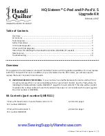
Sixteen C-Pod
Brand: handi quilter Pages: 11

CVA 6805
Brand: Miele Pages: 108

WMD 261 W
Brand: Beko Pages: 40

WMB61021S
Brand: Beko Pages: 40

WMB81431LW
Brand: Beko Pages: 40

119-2
Brand: Singer Pages: 15

112W145
Brand: Singer Pages: 13


