1/8
g
Please read this manual carefully, also with related manual for the machinery before
use the controller.
g
For installing and operating the controller properly and safely, qualified engineers
are required.
g
Please stay away from arc welding equipment, in order to avoid electromagnetic
interference and malfunction of the controller.
g
Keep room temperature bellow 45°c and above 0°c
g
Do not use in humidity below 30% or above 95% or dew and mist places.
g
Please turn off the power and unplug the power cord, before install the control box
and other components,
g
To prevent interference or electric leakage accidents, please make the ground work;
the power cord ground wire must be securely connected to earth by an effective
way.
g
All parts for the repair provided by the Company or approved before use.
g
Please turn off the power and unplug the power cord before any maintenance
action. There is dangerous high voltage control box, you must turn the power off
after one minute before opening the control box.
g
The symbol
in this manual means Safety Precautions, please pay attention to it
and strictly follow it, to avoid any unnecessary damage.
K4 Operation Manual
1 Installation Instructions
1.1 Product specifications
Product Type
AHE59
Supply Voltage
AC 220 ±
V
Power frequency
50Hz/60Hz
Maximum output power
550W
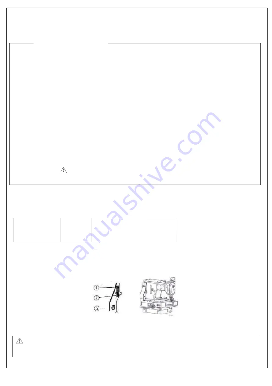
1.2 Interface plug connections
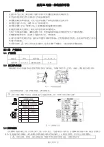
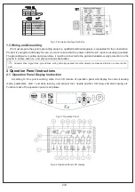
Connecting the plugs of pedaland machine head to the corresponding sockets at the back of controller, as
Figure 1-2. Please check and confirm the plug is inserted firmly.
Fig.1-1 Controller Socket Diagram
ķ
Presser Foot lifter solenoid socket;
ʓ
Solenoid socket ;
ʔ
Pedal socket;
喚
If it is difficult toinserted plug into socket, please check whether them are matching with each other, or the inserting direction
or needle insertion direction is correct!
Safety Instruction
Summary of Contents for JK-K4-UT
Page 1: ......
Page 2: ...0 51 1 1 YKXOKY YK SGT GR...
Page 22: ...20 51...
Page 36: ...34 51 YKZ YIXK IXGTQ JOYQ JXO K IUTTKIZOTM XUJ T Z T Z...
Page 40: ...38 51 Moving cutter is parallel to the fixed cutter Screw1 Screw3 Screw4 Screw2 Fixed cutter...
Page 41: ...39 51 JP YZ IROV GTJ VXKYY XK YNKKZ clip Pressure sheet clip is parallel to the fixed cutter...
Page 47: ...45 51...
Page 48: ...46 51 SS...
Page 50: ...48 51...
Page 52: ...50 51...
Page 53: ...f 9 g g g g g g g g g g...
Page 54: ...1 11 2 12 13 14 15 16 17 8 8 8 8 8 8 8 8...
Page 55: ...3S...
Page 68: ...XVKLQJ DVVHPEOLHV...
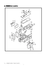
Page 70: ...UDPH DVVHPEOLHV...
Page 72: ...RYHU DVVHPEOLHV...
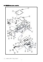
Page 74: ...ORWK SODWH DVVHPEOLHV...
Page 76: ...RRN VKDIW DVVHPEOLHV...
Page 78: ...0DLQ VKDIW DVVHVPEOLHV...
Page 80: ...1HHGOH EDU DVVHPEOLHV...
Page 82: ...1HHGOH JXDUG DVVHPEOLHV...
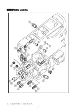
Page 84: ...HHG PHFKDQLVP...
Page 86: ...1HHG PHFKDQLVP...
Page 88: ...3UHVVHU IRUP DVVHPEOLHV...
Page 90: ...1HHGOH IHHGLQJ DVVHPEOLHV...
Page 92: ...7KUHDG ORRVLQJ DVVHPEOLHV RQH...
Page 94: ...7KUHDG ORRVLQJ DVVHPEOLHV WZR...
Page 96: ...7KUHDG ORRVLQJ DVVHPEOLHV...
Page 98: ...DP DVVHVEOLHV...
Page 100: ...XEULFDWULRQ DVVHPEOLHV...
Page 102: ...2LO SXPS DVVHPEOLHV...
Page 104: ...6LOLFRQ RLO GHOLFH DVVHPEOLHV...
Page 106: ...DXJH VHW VSHFLILF SDUWV...
Page 108: ...QLIH KROGHU DVVHPEOLHV...
Page 111: ...7RS ZLSHU DVVHPEOLHV...
Page 113: ...6ROHQRLG DVVHPEOLHV...
Page 115: ...OHFWURQLF FRQWURO DVVHPEOLHV...
Page 117: ...IWHU FDP DVVHPEOLHV...
Page 120: ...IWHU ILJKW FDP DVVHPEOLHV...
Page 122: ...7KUHDG SRRO VVHPEOLHV...
Page 124: ...35AC 35ACFT device...
Page 126: ...35AC 35ACFT device...
Page 128: ...FFHVVRULHV DVVHPEOLHV...
Page 130: ...HGSODWH DVVHPEOLHV...

