


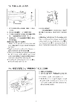
13
4
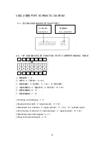
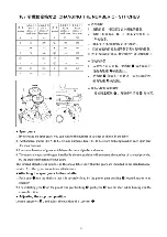
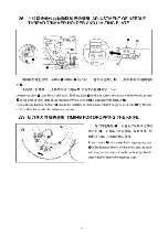
端口示意图
PORT SCHEMATIC DIAGRAM
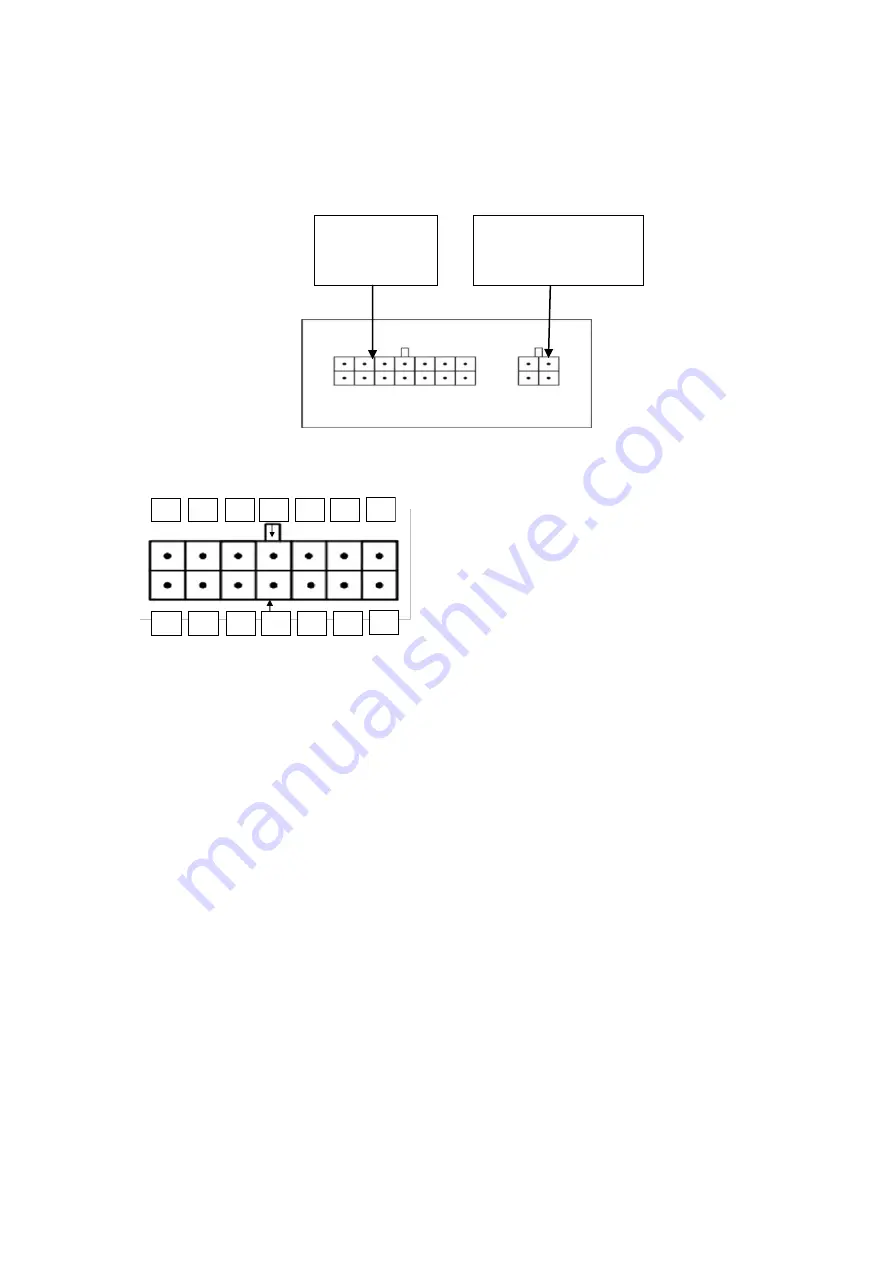
4.1
:各个端口名称
NAMES OF EACH PORT
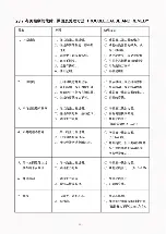
4.2
:
14P
功能端口对应表
FUNCTION PORT CORRESPONDING TABLE
14
13
12
11
10
9
8
7
6
5
4
3
2
1
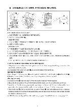
①
线电磁铁:
1
、
8
②
衣车灯:
2
(信号地)
、
9
(
+5v
)
③
机械锁感应:
5
(信号地)
、
11
(
+5v
)
、
12
(感应信号)
④
大盘结束感应:
3
(感应信号)
、
4
(信号地)
、
10
(
+5v
)
⑤
机械锁电磁铁:
6
、
13
⑥
抬压脚电磁铁:
7
、
14
①
Trimming electromagnet
:
1
、
8
②
Sewing machine light
:
2
(
signal ground
)
、
9
(
+5v
)
③
Mechanical lock induction
:
5
(
signal ground
)
、
11
(
+5v
)
、
12
(
induced signal
)
④
End induction of crank set :3
(
induced signal
)
、
4
(
signal ground
)
、
10
(
+5v
)
⑤
Mechanical lock electromagnet
:
6
、
13
⑥
Presser foot electromagnet
:
7
、
14
14P
功能端口
Function Port
14
function
port
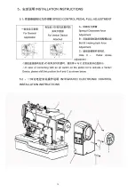
脚踏板端口
Foot Board Port
Speed controller port
Summary of Contents for JK-T718E
Page 1: ......
Page 20: ......
Page 23: ...17...
Page 26: ...20...
Page 34: ...28...
Page 37: ...76...
Page 39: ...2 MAIN SHAFT COMPONENTS 30 30 3 24 13 45 3...
Page 41: ......
Page 43: ......
Page 45: ...5 NEEDLE BAR FRAME COMPONENTS 16 ss C 9...
Page 47: ...6 OVEREDGING WIDTH ADJUSTING COMPONENTS 5 43 45 11...
Page 51: ...8 BOBBIN THREAD TRIMMER COMPONENTS 1 35 39 40 20 18 21 21 1 15...
Page 53: ...9 KNIFE BAR COMPONENTS 9 13 54 55 56 59 1_1 64 65 ___66 63 33 17...
Page 54: ...18 P01011...
Page 55: ...10 FEED CAM TRIPPING SEGMENT COMPONENTS 47 1 Q 17 12 25 6 6 50 19...
Page 57: ...11 CONTROL BOX COMPONENTS...
Page 59: ...12 SAFE PROTECTION COMPONENTS...
Page 61: ...25...


