background image

JackaJay 

INSTALLATION GUIDE

32

7 Troubleshooting

Ensure that you have attempted to return to the associated installation 
section and attempted to locate the reason / cause of the fault that you are 
experiencing.

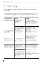
Furthermore, please refer to the list below for some troubleshooting checks, if you 
are unable to solve the issue and for any major troubleshooting issues or queries, 
kindly contact your local provider or Jack Industries for additional direction.

Issue Experience

Cause

Remedy

Controller will not turn ON. Incorrect polarity 

connection at 
the battery.

Check that the Positive and 
negative connections at the 
battery are correct. It may also 
have damaged an internal 
protection fuse. 
Contact Jacka Industries. 

Power supply plug is not 
pushed in completely at 
the controller.

Unplug the power lead from 
the controller and reinsert it 
until it clicks.

Camper roof lifts and the 
controller trips out on Low 
Battery voltage.

The campers battery 
is discharged and / or 
aged and faulty.

Replace the battery, provide 
external 240V supply to BMS 
system for charge or use the 
supplied emergency jumper 
cable to connect the JackaJay 
controller to an external 12V 
supply (car battery).

During commissioning, 
3 motor drives go the 
correct way and one 
backwards.

Incorrect polarity of the 
motor connection will 
cause reverse drive.

Remove the motor cover 
and check the connections. 
Connection with the RED dot 
should have the RED core on it. 
If incorrect, change them over 
and ensure a tight connection.

Keeping getting Fault 
indication on one corner, 
after initial installation. 

Incorrect motor or 
limit switch coloured 
connections on corner 
drive actuators. 

Check the connections and 
colours, correct them if need 
found to be wrong, be advised 
that this error may damage 
the drive mechanism, if loud 
knocking (not taping) is 
heard during lift sequence a 
replacement drive tube will need 
to be purchased. 

The drive block is not 
stopping when it should, 
it is overdriving, bending 
the limit switch arm and 
striking the emergency 
stop bracket.
Incorrect coloured 
connections.

Summary of Contents for JackaJay

Page 1: ...Installation Guide Version 5 0 2018 Jacka Industries Pty Ltd All rights reserved...

Page 2: ...ormation Please refer to www jackaindustries com or make contact via email at enquires jackaindustries com for the most current information From the Web site you may also download and refresh this doc...

Page 3: ...tallation guides 3 2 Identify a flat and level location 10 3 3 Expose manual winch system 10 3 4 Set roof height and install corner supports 11 3 5 Remove the manual winch system 13 4 Installation of...

Page 4: ...ated components Removing the manual winch lift system and upgrading to a fully automatic electric lift system This note issues a WARNING to the installer of any impending DANGER EVENT that has the pot...

Page 5: ...ACL You are entitled to a replacement or refund for a major failure and compensation for any other reasonable and foreseeable loss or damage You are also entitled to have the goods repaired or replac...

Page 6: ...anty Section Task 1 0 Introduction 2 0 Preparation 3 0 Installation Setup Set Roof Height and Remove old Winch system 4 0 Install the JackaJay lift system 5 0 Test and commission the JackaJay lift sys...

Page 7: ...d the van During installation it is required that JackaJay kit componentry must be sourced prior to installation Please see the list below in this section Battery Drill Screw Drivers 3 8 90 Drill opti...

Page 8: ...corner elbows 16 x 14G 10 x 25mm Hex head self drilling timber screws motor assemblies 16 x M6 x 30mm Cap head bolts nuts and washers motor assemblies 4 x 8G x 20mm self drilling screws control box 4...

Page 9: ...you in ensuring that no pieces are missing This guide will show you all that is required It is critical when putting up a camper trailer to always ensure that you have a flat and level location and i...

Page 10: ...o 3 4 Set roof height and install corner supports Ensure the roof is lifted to its normal height and the side door is lowered into the side wall of the camper and is closed The measurement required fo...

Page 11: ...masts with long cable ties rope heavy duty duct tape etc Once your timber corner supports are secured carry out a check on the side door operation position them and check your canvas is not too tight...

Page 12: ...h to keep the old system and the cables are in good condition unscrew the 4 x hooks eyelets holding the cables Release the cable from the hooks If not use the Bolt Cutters to cut the 4 x cables close...

Page 13: ...l not be released into the living area of the Camper Trailer Remove all bolts and screws from the old winch system and remove the winch square tubes flexible springs pushrods cables pullies and corner...

Page 14: ...se a variety of screws bolts with washers and nuts to ensure secure attachment of corner elbows and motor assembly If the floor timbers are substantially damaged you MUST repair the floor to ensure th...

Page 15: ...SITIONS POSITION FOR EACH COLOR DRIVER S SIDE FRONT DRIVER S SIDE REAR PASSENGER SIDE FRONT PASSENGER SIDE REAR 4 1 Corner Bend Installation Position but DO NOT fix to the floor 4 x Corner Elbows blac...

Page 16: ...varies due to corner height variation Position something heavy enough to hold the spring pushrod temporarily in position Locate one full set i e RED Drive tube and RED motor assembly Check that they...

Page 17: ...d to the correct position All Bronze Drive Blocks must be in the same position i e Bronze drive block MUST be 1 2mm from the micro switch roller 1 2mm Position the Square Drive Tube Assembly roughly i...

Page 18: ...switch end into the Flexible Spring Pushrod that protrudes from the corner elbow Firmly push the entire JackaJay assembly towards the corner elbow until it STOPS The end of the square drive tube assem...

Page 19: ...ing corner assemblies STOP POINT 12 You MUST have all lift mechanisms including corner elbows flexible pushrods square drive tubes and motor assemblies laying in their correct positions It is imperati...

Page 20: ...the pilot drill passes through timber use M6 bolts washers and nuts Or use the 14G 10 x 25mm Timber screws Use Hex Nut driver to firmly drive in appropriate screws to attach corner Elbow permanently t...

Page 21: ...sembly and apply firm pressure to the lift mechanism and check your pilot holes If they line up firmly drive in the selected appropriate 3 x screws for a selected forth hole drill the floor out with a...

Page 22: ...MUST be adjusted Are the motor couplers tight as well as the couplers grub screws IF ANY OF THE ABOVE CHECKS ARE NOT ACCURATE IT MAY AFFECT THE OPERATION OF THE JACKAJAY LIFT SYSTEM 4 5 INSTALLING CO...

Page 23: ...uitable location in the panel boot back walling panelling Note sometimes drilling a 32mm hole through the side panel and into the winch winder cavity can be suitable also It depends on the design of y...

Page 24: ...ors they are cut at different lengths to match the limit switch male connection points 4 5 2 1 FRONT HARNESS Green Red STOP POINT 16 Ensure the correct colour plugs are attached to the correct coloure...

Page 25: ...Rear Harness behind the refrigerator cabinetry and or oven This will involve passing through panelling cut outs the tube behind the fridge etc Don t pull too hard if the edge fouls find the obstructi...

Page 26: ...tely engaged i e a click should be heard when pushing in Physically install the Power harness as required from the JackaJay controller area to the Battery or selected power source Whether it is in the...

Page 27: ...ower Harness cores with the power source Ensure that the correct polarity is observed RED Positive 12V DC BLACK Negative 0V DC Dress any remaining cabling in and tie back any slack area to a safe posi...

Page 28: ...LE Go and check all 4 x corner lift mechanisms The Bronze block should not be visible near the limit switches It will have travelled down the square tube If a bronze block is visible near the micro sw...

Page 29: ...ouchscreen if it has timed out and conduct an Automatic ROOF LOWER function Press and HOLD the ROOF LOWER button STOP POINT 19 The roof is now permanently set to Upper Automatic roof height point for...

Page 30: ...or Jacka Industries Pty Ltd for direction Replace all panels cabinetry and upholstery And untie curtains Remove the plastic hatch cover where the old winch handle was used to wind up the roof Replace...

Page 31: ...all Deutsh plugs at the bottom of the controller and confirm they are secure and dusts covers are adequately positioned Check the touch screen for any impact damage and functionality Check the Motor...

Page 32: ...e The campers battery is discharged and or aged and faulty Replace the battery provide external 240V supply to BMS system for charge or use the supplied emergency jumper cable to connect the JackaJay...

Page 33: ...t to find the cause of the additional strain on the system Contact Jacka Industries to discuss Roof height may have been set too high initially The end of the coloured drive actuator once installed an...

Page 34: ...as similar weights Hence heavier corners will drive slightly slower This is okay if the system is still operating and the roof height will level out at the top Ensure that the roof weight is evenly di...

Page 35: ...Thank you from Mal Stu and families Happy caravaning...

Page 36: ...Jacka Industries Pty Ltd 468 Hawkesbury Rd Winmalee NSW 2777 1300 052 252 www jackaindustries com 468 Hawkesbury Road Winmalee 2777 NSW Australia 1300 052 252 www jackaindustries com...

Reviews: