background image


Plasma 33 H 


Operating Manual 


Page 11 

11. Trouble-Shooting 


Warning!

  Defects at the electrical unit may only be repaired by a specialist. 
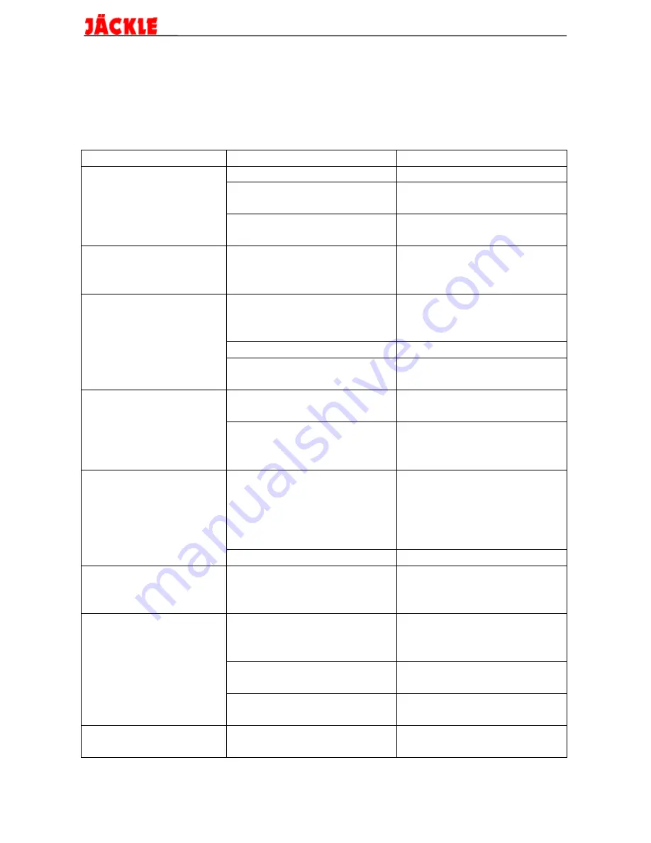
 
 
Trouble 

Cause 

Remedy


Mains connected and 

mains fuse is faulty 

check mains fuse 

main switch turned  

mains cable is 

check mains cable 

on / fan doesn't run 

interrupted 


fuse F1 at auxiliary 

change fuse F1 


transformer is faulty 

(2 A slow / 250 V) 

Fan is running / 

light bulb is faulty 

check / change light bulb 

mains lamp does not 


come on 


No function when 

parts at the torch head 

check torch head 

torch trigger is 

are incompletely mounted 


pushed, even the 

(safety circuit) 


contactor doesn't 

torch trigger defective 

check torch trigger 

switch 

torch trigger control   

check torch trigger  


lead interrupted  

control lead 

Malfunction lamp 

insufficient pressure  

remove shortage of  

comes on when torch 

air supply 

compressed air 

trigger is pushed 

overheating of the  

unit is ready for work 


machine 

again after ca. 5 minutes 


if fan is running 

Mains contactor  

machine is running  

check mains fuse 

switches when torch 

on 2 phases (mains 

check mains leads 

trigger is pushed, 

fuse is faulty, one 


but pilot arc 

mains lead is 


doesn't arise  

interrupted) 


torch parts defective 

check / change torch parts 

Pilot arc is  

workpiece lead not 

attach the workpiece clamp 

burning / cutting 

connected 

to the workpiece 

arc does not arise 


Cutting arc is burning / 

bad earthing contact 

check / clean earthing   

poor cutting quality 

at the workpiece 

contact (rust, paintwork,  

or insufficient  


oil, grease) 

cutting power 

insufficient pressure  

check pressure air supply 


air supply 


plasma nozzle or  

check / change plasma nozzle 


electrode has burnt out 

electrode 

Cutting arc switches 

cutting speed too 

see chapter 7.2 Cutting 

off 

slow 


Summary of Contents for Plasma 33 H

Page 1: ...Plasma Cutting Unit Plasma 33 H...

Page 2: ...ent work with the Plasma 33 H cutting unit Please read the instructions carefully prior to initial operation of the unit The information contained in this manual should be made available to all operat...

Page 3: ...e corresponds to the safety requirements of the recommendations Name of unit Plasma Cutting Unit Type of unit Plasma 33 H Relevant EMC recommendation 89 336 EEC EC recommendations modified by recommen...

Page 4: ...rvice and Maintenance 8 9 Functional description of the control PCB 9 10 Error messages of the control PCB 10 11 Trouble Shooting 11 12 Spare Parts 12 13 Spare parts torch PSB 31 HF S 14 14 Circuit di...

Page 5: ...l from the kerf A clean clear cut is the result 1 2 Advantages Time saving due to high cutting speed in cutting thin sheet metal if compared to oxy fuel gas cutting nibbling or sawing Heat build up is...

Page 6: ...preferably fitted below the cutting zone should be provided The cutting area of the workpiece has to be cleaned and free of solvants and degreasing agents to prevent the formation of toxic gas The use...

Page 7: ...e 449 50939 K ln Furthermore we point out that in some operative ranges where despite the observance of radiation limits this cutting unit can cause electromagnetic interferences which are the respon...

Page 8: ...g as plasma gas and for another as a cooling medium for the torch body to protect against high thermic load HF ignited pilot arc A pilot arc which is initiated by a high frequency spark starter ensure...

Page 9: ...A 92 V Max cutting thickness quality cut 7 mm severance cut 10 mm System of protection IP 23 Insulation class H 180 C Type of cooling F Dimensions L x W x H mm 350x230x350 Weight 30kg Compressed air s...

Page 10: ...ressure Pay attention to a sufficient pressure and a sufficient flow quantity of the pressure air supply Besides the air must be as free as possible from oil and water Warning The water tanks must be...

Page 11: ...e pilot arc is ignited When the pilot arc touches the workpiece the cutting arc arises If the cutting arc does not arise the pilot arc automatically switches off after ca 2 seconds Warning Don t repea...

Page 12: ...hold the manual cutting torch sloped and then change into vertical position in order to reduce spatter formation on the plasma nozzle 8 Service and Maintenance This cutting unit should be serviced in...

Page 13: ...unctions The LED D2 5V indicates the correct voltage on the PCB The LED D3 OK shows the normal function of the microprocessor The LED D4 BT shows the function of the torch trigger and the possible err...

Page 14: ...ight Torch trigger is pressed Error functions 1x flash The cutting transformer has turned off no cutting current 2x flash The reed contact has turned off no cutting current 3x flash Reed contact is fa...

Page 15: ...p insufficient pressure remove shortage of comes on when torch air supply compressed air trigger is pushed overheating of the unit is ready for work machine again after ca 5 minutes if fan is running...

Page 16: ...Plasma 33 H Operating Manual Page 12 12 Spare Parts Picture 12 1 Sideview...

Page 17: ...g in socket green 712 024 002 Bulb 24 V 463 024 012 17 Main switch M225 645235 440 220 033 Grip for main switch 440 225 051 18 Housing bonnet 715 021 007 Case handle 305 179 005 19 2 channel blade ter...

Page 18: ...742 0011 12 2 Insulating sleeve for HF version 742 0038 17 Cap 742 0004 18 Spring 742 0089 21 Safety clamp cpl 742 0099 30 Handle with single action switch 742 0044 consisting of Handle left and right...

Page 19: ...3 14 workpiece torch 06 02 04 K1 14 H1 H2 Mains lamp Malfunction lamp A1 A2 A3 C1 Ignition unit SIG 3 6 HF terminating PCB P1 H Capacitor 2 2 F 250V F1 F2 Fuse PCB PL 3 S1 Torch trigger Thermal switch...

Reviews: