REMOTE SENSOR INSTALLATION INSTRUCTIONS
The T-32-P can use an indoor remote sensor or multiple sensors for temperature averaging, or as an
outdoor sensor for temperature display or a control function depending upon the thermostat
configuration.
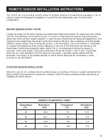
Locate the sensor in the same manner as a thermostat. Mount the sensor 18” away from any outside
wall. Do not install the sensor behind doors, in corners or other dead air spaces. Keep the sensor
away from direct air flow, supply registers or near sources
INDOOR SENSOR INSTALLATION
of heat such as lamps and appliances. The
maximum wire length from the sensor to the thermostat is 300 feet. Use a separate 18-2 thermostat
cable for sensor wiring. Prior to wiring the sensor to the thermostat, use an ohm-meter or multimeter
to measure the resistance of the sensor. Measure at the end of the wires that will connect to the
thermostat. Confirm the resistance value (within 5%) to the temperature where the sensor is
mounted. Disconnect power to the thermostat when wiring the sensor to the ‘T’ and ‘T’ terminals.
Strip only as much insulation off of the wires as necessary to provide a good contact with the
terminals. The sensor is not polarity specific so either sensor lead may be connected to either
terminal on the thermostat.
Mount the sensor on a vertical exterior surface below an overhang. Choose a location protected from
direct sunlight and exposure to excessive moisture. Follow the same wiring and test procedures as
installing an indoor sensor.
30
34.6
70
11.9
40
26.1
80
9.4
50
19.9
90
7.4
60
15.3
100
5.9
OUTDOOR SENSOR INSTALLATION
SENSOR CALIBRATION CHART
Temperature
Resistance
Temperature
Resistance
(°F)
(k )
(°F)
(k )
Ω
Ω
16

