5418 Elmwood Avenue, Indianapolis, IN 46203-6025
Toll Free: 888.652.9663 Fax: 317.227.1034
www.jacksonsystems.com
8
Short Cycle Protection
The Limit Stat™ has built-in short cycle protection
designed to prevent compressor damage due to
rapid switching of modes or momentary power
outages. Short cycle time delays are fixed at 5
minutes on and 5 minutes off.
Under normal use, the Limit Stat™ requires no
special maintenance. The LSL-HCB, battery
powered model requires that the batteries be
replaced at least once per year or whenever the
“LO BAT” symbol appears on the LCD.
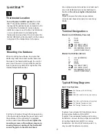
To replace the batteries, release the thermostat
from the subbase by pressing the thumb latch
located at the bottom of the unit and swinging the
thermostat up and away from the subbase.
Remove the used batteries from the battery tray
and discard appropriately.
4
This installation manual should not be left with unauthorized users as it contains installer setup functions which,
if not correctly set, may cause damage to the HVAC equipment or seriously affect performance.
The Limit Stat™ thermostat is intuitive, reliable and easy to install. Using a common sense approach to the installation will
ensure this product is installed properly and to the customer’s satisfaction. Please take time to read and understand this
manual so that installation and testing is undertaken in an efficient manner.
Although great care has been taken in preparation of this manual, Jackson Systems takes no responsibility for
errors or omissions contained herein. It is the responsibility of the installer to ensure that this thermostat and the
equipment connected to it operate in a safe and efficient manner.
©
Due to ongoing product improvements, Jackson Systems reserves the right to change the specifications of the Limit
Stat™ thermostat or its components without notice.
All rights reserved.
Jackson Systems, LLC 2010
Intellectual rights apply.
9
Maintenance
Install two new AA Alkaline batteries into the
battery tray. Match the battery direction with the
polarity markings on the battery compartment to
ensure proper operation. When finished, replace
the thermostat on the subbase by lining up the two
holes in the top of the thermostat with the two
hooks on the top of the subbase. Slowly pivot the
bottom of the thermostat towards the subbase and
push firmly until the thermostat is securely latched
to the subbase. Do not attempt to force the two
halves together.
This thermostat must be wired in accordance with
all applicable local codes and ordinances.
The thermostat should be limited to a maximum of
1.5 amps. Higher current may cause damage to
the thermostat.
10
Important Installation Notes
06-1057-033010


