background image

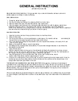
GENERAL INSTRUCTIONS 

(INSTALLATION / DIMENSIONS) FOR 100B, PRB SERIES  

NOTE: Read the following instructions carefully. Proper installation of your Jackson Dishwasher will assure proper 

machine operation. 

1.   Open side doors, the front door (hook open) and remove dish, cup, and glass racks, and set to one side for       

later use. Remove the tape holding the overflow strainer, the pump intake strainer, the wash head assembly 
and the rinse head that are inside the machine. 

2.   Cut straps holding machine to base of crate, ease machine on to floor and slide into place of installation. 
3.   Connect drain to bottom of machine (1 1/2" IPS female fitting on bottom of wash sump) with proper slope to 

conform with local and/or national codes. Drain is a gravity feed system from machine. 

4.   The incoming water line to the unit must be 3/4" with the capacity to supply 12 gallons  per minute with a flow  

rate of 20 PSI. The temperature at the unit must be 140° F. • This connection is just before the Y-strainer. 
Connect to conform with local and/or national codes (STANDARDS). 

5.   Electrical connections should be made through hole in bottom of control box to terminal board inside (to the 

right lower side of control box). This terminal board is accessible by removing the lower cover plate on control 
box. The terminals are marked L1, L2 (requiring 208-230V, single phase), or L1, L2, L3 (requiring 208-230V, 
three phase). There is a grounding lug inside of the control box on the bottom left. Be sure all connections 
made are tightened properly. Refer to data plate for Voltage and Amperage totals and whether machine is 
designed for 50 or 60 cycle operation. 

6.   Install the proper circuit breaker, wire, and conduit size to conform with local and/or national codes. Refer to 

data plate for electrical loads. 

7.   DO NOT APPLY POWER UNTIL STEP 10. 
8.   Insert pump intake strainer and overflow strainer, then close door. 

  9.  Turn on hand valve controlling water supply to machine; check for any leaks in plumbing 

and connections.  

10.   To energize electrically, proceed as follows: 

a.  Turn on customer's circuit breaker controlling machine. 

  b.    Check voltage at incoming terminal L1, L2, and L3 (if applicable). It should match 

data plate voltage. Voltage at L1 and L2 should be checked to ground individually to 
ensure that a high (or wild) leg is not connected to L1 or L2. (Voltage exceeding 150V 
to ground would indicate high leg).  

c.    If voltages are in required range, turn on 15 amp circuit breaker on side of control

 box.


                The 15 amp circuit breaker protects and controls the motors and control circuit only; 

       it is not meant to protect or control the rinse heaters.  
d.  Insert a rack into the machine and close all doors.  
e.   Turn on the master switch; this supplies voltage to       the operating controls. Then lift up on the rinse/fill     

switch. The unit will automatically fill the wash tub with water to a specific level.  

f.    Open the front door and check the water level. It should be 1/4" below overflow level. 

 If not, close doors, check the incoming water line making sure that the solenoid valve 
 fully opens and closes as the switch is turned on and off.  

g.   If the water is at the proper level, with the front door closed, turn. on the heat switch. 

Observe the temperature gauges; the rinse temperature should rise to the specified level 
of 180° within five minutes if the incoming water temperature is 140° to the booster 

                 tank. 

h.  The wash heater will take longer to reach 150°F, as the element is designed for maintaining 

temperature, not heating.  

i.  Turn the manual wash switch on with the door closed. You should hear the water being pumped as it 

strikes the top of the machine. Turn off the manual wash switch.  

j.   The unit is now ready to proceed with the washing of dishes in accordance with the 

operating instructions in this manual, and the instruction sticker on the front door of 

the dishwasher. 


Summary of Contents for 100 B/PRB

Page 1: ...r Installation Requirements Maintenance and Care Operating Instructions Illustrated Parts List Description of Components Electrical Diagrams WORLD HEADQUARTERS MANUFACTURING OPERATIONS Highway 25E P O...

Page 2: ...MPS 20 REPLACING SEAL and CERAMIC on RINSE PUMPS 22 INSTRUCTIONS for ADJUSTING TENSION of CANTILEVER 24 APPLYING NYLATRON STRIP TO 100 SERIES DOOR 26 WATER LEVEL CONTROL For Rinse Tank 27 WATER LEVEL...

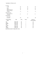
Page 3: ...y Gallons 12 12 12 Rinse Tank Capacity Gallons N A 3 3 Wash Pump Capacity Gal Per Min 188 188 188 Thermometers Wash F 140 160 140 160 140 160 Rinse F 180 195 180 195 180 195 Water Requirements NSF Rat...

Page 4: ...19 3 4 x 19 3 4 2 2 2 Combination 2 2 2 Shipping Weight Approximate basic model 400 400 400 Electrical Rating Model Volts Cycle Phase Maximum Total Load Amps 100 208 or 220 60 1 16 100B 208 or 220 60...

Page 5: ...p intake strainer and overflow strainer then close door 9 Turn on hand valve controlling water supply to machine check for any leaks in plumbing and connections 10 To energize electrically proceed as...

Page 6: ......

Page 7: ...detergent dispenser is used follow the manufacturer s instructions 7 Lower all of the doors 8 Start the automatic wash and rinse cycle of the dishwasher by flipping the start switch in a full up or do...

Page 8: ...e and allow to run for two minutes then again drain the wash reservoir g Refill as it is ready for regular operation 2 Clean strainers Three times per day a Clean around overflow and pump intake strai...

Page 9: ...10 Lift and remove large manifold with long length tubes similar to step 8 11 The lower fixed race may be left in place 12 Clean ball bearings by soaking in de liming solution 13 Ball bearing race wa...

Page 10: ...art as wash cap is removed ITEM P N DESCRIPTION ITEM P N DESCRIPTION ITEM P N DESCRIPTION 1 0126800 End Plug 7 0137000 Rinse feed pipe coupling or nut 13 0194500 Spray tube 16 2 0136000 Rinse arm body...

Page 11: ...om the control box by loosening the four screws holding it Hang the control panel using the two right hand screws with the back side of the panel outward If it is determined that the timer is defectiv...

Page 12: ...ove motor leads from connection points 2 Remove the two screws which hold the motor 3 Replace with new motor 4 Re connect motor leads to proper points NOTE It may be necessary to remove complete timer...

Page 13: ...osite position Cycle light P N 0083500 This light comes on only when automatic cycle is in progress and extinguishes when cycle is complete Manual wash switch P N 0155500 This switch is used to by pas...

Page 14: ...ted in individual round holes with a keyway By using a pair of pliers or open end wrench it is possible to loosen the inside nut enough to allow the outside nut holding the switch to be removed by fin...

Page 15: ...either direction then if screw 1 stopped while turning in CW direction turn screw 2 in CW direction slowly and only 1 8 of a turn or less per complete cycle of the unit if screw 1 stopped while turnin...

Page 16: ...dge can now be lifted out Be careful not to damage the machined faces while the valve is apart TO REASSEMBLE Place the diaphragm cartridge in the body with the pilot port extension UP Hold the plunger...

Page 17: ...machine circuit breaker located on right side of control box b Remove lower cover plate on control box held by single screw c Make sure rinse temperature is below 180 preferably about 140 d Reapply po...

Page 18: ...tions 3 Check power at positions 6 and 7 Voltage should be approximately 220V If not check wires for breaks or bad connections 4 Temperature should rise as explained in A1 and amperages may be checked...

Page 19: ...3 If step one or two does not correct the problem proceed as follows a Turn off power to machine by tripping customer circuit breaker to off position Turn machine circuit breaker on right side of con...

Page 20: ...V to ground 4 Check power at position 6 voltage should be 220V approximately if not check wires for breaks and bad connections 5 Temperature should rise as explained in AA1 and amperages may be checke...

Page 21: ...moved with the mounting plate c Turn over the plate and push the seal and or ceramic out of the housing carefully It may be necessary to break the ceramic to remove it d Clean the hole where the ceram...

Page 22: ...RUBBER 4 0108000 SNAP RING 5 0105000 CERAMIC FACE w O RING 6 0104500 PUMP MOUNTING PLATE 7 0105000 SEAL FACE 8 PLATE TO MOTOR MOUNTING BOLTS LOCKWASHERS 9 0105000 SEAL ASSEMBLY SEAL SPRING CUP WASHER...

Page 23: ...e direction 8 The ceramic is embedded in the impeller and normally does not need replacement but it should be checked for cracks or a worn out surface If ceramic does need replacement proceed as follo...

Page 24: ...ATE 3 0089000 PUMP CERAMIC FACE w RETAINER CUP 4 0087500 PUMP IMPELLER SEAL 5 0089500 PUMP IMPELLER 6 0090000 PUMP MOUNTING GASKET 7 0090500 PUMP PLATE TO MOTOR MOUNTING BOLTS 8 0091000 MOUNTING PLATE...

Page 25: ...to remove doors to completely clean channel If so remove only one door at a time Make sure cantilever has stop to prevent pulling other door up and out of channel If it does not have stop secure cant...

Page 26: ......

Page 27: ...NE ADHESIVE OR ANY GOOD NON HARDENING GLUE SHOULD BE LAID ON THE INSIDE OF THE DOOR GUIDE S SURFACE TOP AND BOTTOM MAKING SURE THAT NONE OF THE EXPOSED SURFACE TO THE OUTSIDE HASANY GLUE ON IT TAKE TH...

Page 28: ...one of the following problems exist this control should be checked out as shown below 1 Water to rinse tank runs continually with the master switch on 2 Water does not flow into rinse tank when requir...

Page 29: ...noid or rinse pump Simultaneously the contacts will close on the normally open circuit energizing the wash rinse heat circuit Checkout and information concerning that part of the circuit are in the wa...

Page 30: ...ional and other causes should be explored EXAMPLES 1 Loose or broken wire to probe or ground green wire 2 Dirty probe s 3 Solenoid faulty see instruction page concerning solenoid 4 Thermostat faulty o...

Page 31: ...he Solenoid valve 5 Water level control faulty 5 See page on water 6 Y strainer clogged 6 Turn water to machine off remove plug strainer screen clean replace Will not fill with electrical 1 Customer s...

Page 32: ...runs continu 1 Rinse switch sluggish 1 Replace ously with power on or faulty 2 Solenoid valve dirty 2 See special instruc or faulty tions page concerning Solenoid Valve 3 Water level control 3 See spe...

Page 33: ...and control panel 3 Master switch faulty 3 Replace 4 Water level control faulty 4 To check water level control see special instructions on water level control 5 High fill probe 5 Clean or short out p...

Page 34: ...ner conical 2 Replace strainer end of tube bent out of shape 3 Dirt or mineral deposits in 3 See instruction page on strainer hole Preventive Maintenance Wash motor runs but 1 Wash temperature of 150...

Page 35: ...diaphram and plunger flush and clean see instruction page on Solenoid Valves 6 Coil on the solenoid valve is burned out 6 See 5 above 7 Insufficient or excessive pressure 7 Check flow pressure which...

Page 36: ...control clock original factory setting wise for higher setting 5 Thermostat faulty 5 Check thermostat see instruction page 6 Heater faulty 6 Check heater see instruction page 7 Contactor faulty 7 Che...

Page 37: ...he automatic 1 Start switch faulty 1 Check switch Replace if functions work wash rinse necessary see instructions page concerning replace ment of switches in control panel 2 Wire connections poor 2 Co...

Page 38: ...H PUMP MOTOR 50 Cycle 0047000 WASH PUMP MOTOR 60 Cycle 0050900 CUSTOMER S ELECTRICAL CONNECTION 0051000 CUSTOMER S WATER CONNECTION 0055100 RINSE PUMP MOTOR PRB ONLY 50 Cycle 6007900 RINSE PUMP MOTOR...

Page 39: ...0009000 CANTILEVER SPRINGS 4 0012000 CONTROL CIRCUIT PROTECTION DEVICE 15 0084500 WATER LEVEL PROBE PRB ONLY 5 0101800 WATER PUMP MOTOR 50 Cycle 16 0068000 BOOSTER TANK 5 0102000 WASH PUMP MOTOR 60 Cy...

Page 40: ...CE 15 0101800 WASH PUMP MOTOR 50 Cycle 5 0084300 HIGH WATER PROBE 15 0102000 WASH PUMP MOTOR 60 Cycle 6 0169100 WASH RINSE THERMOMETERS 16 0007500 BREATHER TUBE PRB ONLY 7 0011500 CANTILEVER DOOR COUP...

Page 41: ...36000 LOWER RINSE HEAD ASSEMBLY 4 EXTERNAL VACUUM BREAKER PIPING 13 0200000 LOWER WASH HEAD ASSEMBLY 5 0008700 CANTILEVER SPRING ROD 14 WASH TANK NLA 6 0136000 UPPER RINSE HEAD ASSEMBLY 15 DRAIN OUTLE...

Page 42: ...CE 2 0006800 BOOSTER TANK 8 0153700 Y STRAINER 3 DETERGENT SENSOR FITTING 9 0143000 SOLENOID VALVE 4 WASH TANK 10 0101800 WASH PUMP MOTOR 50 Cycle 5 DRAIN OUTLET 10 0102000 WASH PUMP MOTOR 60 Cycle 6...

Page 43: ...SKET 4 0184700 POPPET 5 BODY 1 PROBE BOOT 2 NUTS 3 LOCKWASHER 4 PROBE 5 TANK COUPLING 1 NUT 6 32 S S 2 WASHER RUBBER 3 PORCELAIN OUTER 4 INSERT SILASTIC 5 PORCELAIN INNER 6 STEM ITEM P N DESCRIPTION 1...

Page 44: ...0152000 OVERFLOW STRAINER 4 0058000 WASH TANK HEATER ELEMENT 5 015100 INSIDE PUMP STRAINER 6 WASH TANK THERMOSTAT SHEATH 7 SUMP WALL ITEM P N DESCRIPTION 1 DRAIN FITTING WELDED TO WASH SUMP BOTTOM 2 0...

Page 45: ...US BARS 0058900 3 PHASE CONNECTION 44 ITEM P N DESCRIPTION 1 0006800 BOOSTER TANK B MODEL NEW STYLE NOT SHOWN 2 EXTERNAL VACUUM BREAKER FITTING 3 THERMOSTAT PROBE FITTING 4 0058800 HEATER BUS BARS 1 P...

Page 46: ...45 BOOSTER TANK HEATER ELEMENT P N 0060500 WASH TANK HEATER ELEMENT P N 0058000...

Page 47: ...3500 AUTOMATIC INDICATOR LIGHT 4 0121000 RINSE FILL RELAY 14 0155500 MANUAL WASH SWITCH 5 0121000 WASH MOTOR RELAY 15 0154000 MANUAL RINSE SWITCH 6 0122000 WASH HEATER RELAY 16 0083500 HEATER INDICATO...

Page 48: ...TS THE AUTOMATIC CYCLE WHEN THROWN TO THE CLOSE SIDE OF TH TIMER HOLD TIMER MOTOR RUNS ONE HALF CYCLE THEN OPENS TH TO COMPLETE ONE MACHINE CYCLE TW TIMER WASH TR TIMER RINSE CONTROLLED BY CAMS DRIVEN...

Page 49: ...TANK HEAT WASH HEATER 1 1500 W S SW START SWITCH STARTS THE AUTOMATIC CYCLE WHEN THROWN TO THE CLOSE SIDE OF TH TIMER HOLD TIMER MOTOR RUNS ONE HALF CYCLE THEN OPENS TH TO COMPLETE ONE MACHINE CYCLE T...

Page 50: ...ERMOSTAT CONTROL OF WASH RINSE TANK HEAT WASH HEATER 1 1500W S SW START SWITCH STARTS THE AUTOMATIC CYCLE WHEN THROWN TO THE CLOSE SIDE OF TH TIMER HOLD TIMER MOTOR RUNS ONE HALF CYCLE THEN OPENS TH T...

Page 51: ...WITCH STARTS THE AUTOMATIC CYCLE WHEN THROWN TO THE CLOSE SIDE OF TH TH TIMER HOLD TIMER MOTOR RUNS ONE HALF CYCLE THEN OPENS TH TO COMPLETE ONE MACHINE CYCLE TW TR TIMER WASH TIMER RINSE CONTROLLED B...

Page 52: ...S SW START SWITCH STARTS THE AUTOMATIC CYCLE WHEN THROWN TO THE CLOSE SIDE OF TH TH TIMER HOLD TIMER MOTOR RUNS ONE HALF CYCLE THEN OPENS TH TO COMPLETE ONE MACHINE CYCLE TW TR TIMER WASH TIMER RINSE...

Page 53: ...Box comp wired PR AF2100 1 0020500 Control Box comp wired PRB AF2100 1 0021600 Control Box stripped ONLY AF1149 1 0026500 Control Box front panel wired AF1149 1 0026800 Control Box front panel wired B...

Page 54: ...ey for part 1020 All 1w 0107000 Pump bolt Impeller s s 5 16 18x1 for part 1020 All 1w 0107500 Pump washer Impeller for part 1020 All 1w 0108000 Pump snap ring for part 1020 All 1w 0090500 Pump bolts 3...

Page 55: ...s use 0184301 Conbraco AF13 034 1 0183501 Vacuum Breaker Repair Kit 3 4 Watts use 0184301 Conbraco AF13 034 1 0184300 Vacuum Breaker 3 4 Sloan use 0184301 Conbraco WOO Vacuum Breaker Kit float seal 3...

Reviews: