background image

24

SECTION 5: SERVICE PROCEDURES

RINSE REGULATING THERMOSTAT REPLACEMENT

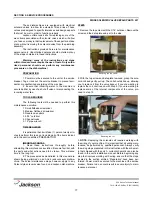
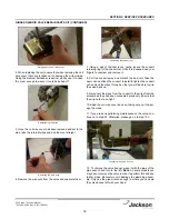
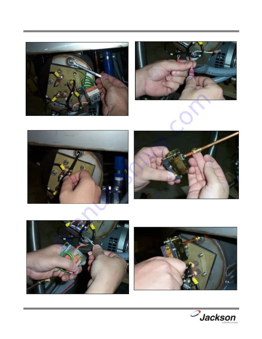
5. Attach the jumper wires to the wires that you removed from
the old thermostat.

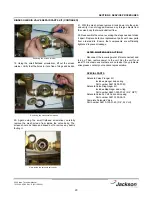
6. Slide the new imperial brass fitting from your kit onto the
new thermostat.

200 Series Technical Manual
7610-100-45-00 Rev. E (02/10/2006)

Removing the imperial brass fitting.

Attaching the jumper wires.

Sliding imperial fitting onto new thermostat.

Pulling the thermostat probe and fitting from the well. 

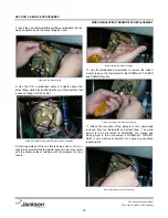
Removing the wires from the thermostat.

Putting the new thermostat in the well.

Summary of Contents for 200B

Page 1: ...MESTIC UNITS ELECTRICALLY HEATED MODELS 200 200B 200LT STEAM HEATED MODELS 200S Jackson MSC LLC P O BOX 1060 HWY 25E BARBOURVILLE KY 40906 PHONE 606 523 9795 FAX 606 523 9196 www jacksonmsc com 200 SE...

Page 2: ......

Page 3: ...bracket from 05700 011 73 72 to 05700 011 81 64 Change rinse thermostat from 05930 12 71 29 to 05930 510 03 79 Delete thermostat mounting bracket and decal from booster tank assembly Added False Pane...

Page 4: ...ly heated high temp hot water sanitizing with booster heater door type dish machine 200 LT Electrically heated low temp chemical sanitizing no rinse booster door type dish machine 200 S Steam heated h...

Page 5: ...RTS SECTION Control Box Assembly 28 Hood Assembly 30 Cantilever Arm Assembly 31 Tub Assembly 33 Rinse Tank Assembly 35 Wash Heaters Rinse Heaters 36 Motor Assembly 37 Frame Assembly 38 Incoming Plumbi...

Page 6: ...1 SECTION 1 SPECIFICATION INFORMATION...

Page 7: ...1 NOTE Typical Electrical Circuit is based upon 1 125 of the full amperage load of the machine and 2 typical fixed trip circuit breaker sizes as listed in the NEC 2002 Edition Local codes may require...

Page 8: ...3 4 9 5 cm 15 1 2 39 4 cm A B 2 7 8 7 3 cm 13 1 2 34 2 cm 75 1 2 191 7 cm 64 162 6 cm 17 3 4 45 1 cm 34 86 4 cm 21 1 8 53 7 cm 25 5 16 64 3 cm FRONT VIEW RIGHT SIDE VIEW TOP VIEW FRONT TOP VIEW CORNE...

Page 9: ...BLE DIMENSIONS CONNECTION TO DISHMACHINE TABLE DIMENSIONS STRAIGHT THROUGH INSTALLATION 20 1 2 52 1 cm OPENING 25 1 4 64 1 cm 2 1 2 6 4 cm 4 10 2 cm MINIMUM 2 1 2 6 4 cm 4 10 2 cm MINIMUM 20 1 2 52 1...

Page 10: ...5 SECTION 2 INSTALLATION OPERATION INSTRUCTIONS...

Page 11: ...r the 200 series models covered in this manual is a gravity discharge drain All piping from the 1 1 2 MNPT connection on the waste accumulator must be pitched 1 4 per foot to the floor or sink drain A...

Page 12: ...place a tag at the disconnect switch to indicate that you are working on the circuit The dishmachine data plate is located on the right side and to the front of the machine Refer to the data plate fo...

Page 13: ...ialist and detergent vendor and come up with a complete training program for operators Using too much detergent has as detrimental effects as using too little The proper amount of detergent must be us...

Page 14: ...pecially for silverware and casserole dishes Place cups and glasses upside down in racks so that they do not hold water during the cycle The dishmachine is meant not only to clean but to sanitize as w...

Page 15: ...on is advised Once the wash tub is drained remove the pan strainers and the pump suction strainer Remove soil and debris from the strainers and set to the side Remove the wash and rinse arm assemblies...

Page 16: ...11 SECTION 3 PREVENTATIVE MAINTENANCE...

Page 17: ...bout how your water hardness will effect the performance of your machine Hard water makes dishmachines work harder and decreases efficiency Again it is important to remind operators that trying to per...

Page 18: ...13 SECTION 4 TROUBLESHOOTING SECTION...

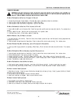
Page 19: ...1 Incoming water supply solenoid not operating Stuck Open Check to ensure that valve is wired correctly If so replace valve Problem Dishmachine fills continuously only when the power is on 1 Incoming...

Page 20: ...t the unit have power to it and live electrical components be exposed USE EXTREME CAUTION WHEN TESTING THE MACHINE Problem Water temperature is less than required 1 Low incoming water temperature Comp...

Page 21: ...16 SECTION 5 SERVICE PROCEDURES...

Page 22: ...his task not including all of the items indicat ed in the section entitled PREPARATION IMPORTANT NOTES 1 Read these instructions thoroughly before attempting this maintenance evolution Become familiar...

Page 23: ...ull the wires through so that you will be able to wire the valve back up 9 Reconnect the wires from the conduit to the wires from the solenoid as they had been connected previously Ensure that the wir...

Page 24: ...not provide information on replacing the solenoid valve 16 Note Even though an O ring may not appear damaged it is a good idea to go ahead and replace it if you have a new one This will help ensure th...

Page 25: ...parts from ordered kits Ensure that components are sufficiently tightened to prevent leakage AFTER MAINTENANCE ACTIONS Reconnect the incoming water if disconnected and turn on Then restore power to t...

Page 26: ...ted that it will take 1 person twenty min utes to perform this task not including all of the items indicat ed in the section entitled PREPARATION IMPORTANT NOTES 1 Read these instructions thoroughly b...

Page 27: ...gotten caught in the threads of both the cap retainer or the vacuum breaker body There is an O ring that should be present on the cap retainer as well Regardless of the condition of the plunger this O...

Page 28: ...RED The following tools may be needed to perform this maintenance evolution 1 3 8 Nutdriver 2 7 16 Combination Wrench 3 Needlenose Pliers 4 Phillipshead Screwdriver 5 Flathead Screwdriver 6 Ratchet wi...

Page 29: ...ew imperial brass fitting from your kit onto the new thermostat 200 Series Technical Manual 7610 100 45 00 Rev E 02 10 2006 Removing the imperial brass fitting Attaching the jumper wires Sliding imper...

Page 30: ...the placement of any covers 10 Use the phillipshead screwdriver to remove the attach ment screws on the thermostat for the NORMALLY CLOSED and COMMON points 11 Attach the ring ends of the jumpers to...

Page 31: ...unau thorized or unqualified personnel may void the warranty Before beginning this or any other maintenance evolution on a unit under warranty you should contact a certified Jackson technician or Jack...

Page 32: ...27 SECTION 6 PARTS SECTION...

Page 33: ...02 10 2006 Jackson 200 SERIES WASH RINSE TEMPERATURE WASH RINSE FILL WASH OFF RINSE MANUAL MODE MANUAL OFF AUTO CYCLE MODE OFF ON POWER HEATER HIGH LIMIT F GND L 1 2 L 3 L USE COPPER CONDUCTORS ONLY 3...

Page 34: ...ash Heater 208 230V 1 PH Not used on 200S 05945 109 02 09 17 1 Relay Rinse Heater 208 230 460V 200B Only 05945 109 01 09 18 1 Decal Ground 09905 011 86 86 19 1 Control Box Weldment with Tric nuts 0570...

Page 35: ...utton 1 2 Dia 05700 011 88 01 4 1 Clamp Double 05700 002 23 89 5 2 Hood Spacer Rear 05700 001 23 06 6 2 Hood Spacer Front 05700 001 23 07 7 2 Front Door Rail 05700 001 20 82 8 4 Hood Support 05700 001...

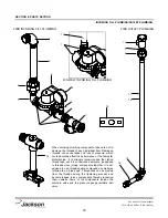
Page 36: ...PARTS SECTION CANTILEVER ARM DOOR ASSEMBLIES 200 Series Technical Manual 7610 100 45 00 Rev E 02 10 2006 3 5 2 1 6 9 15 16 11 12 19 20 18 24 10 11 12 13 17 28 12 18 22 7 8 4 18 23 14 13 10 11 21 3d 3b...

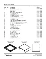
Page 37: ...with Nylon Insert Low Profile 05310 374 02 00 13 2 Sleeve Cantilever Arm 05700 000 85 69 14 2 Plug Cantilever Arm 05340 011 35 00 15 1 Magnet Reed Switch 05930 002 68 53 16 2 Locknut 8 32 S S Hex with...

Page 38: ...3 11 SEE PAGE ENTITLED MOTOR ASSEMBLY SEE PAGE ENTITLED WASH HEATERS RINSE HEATERS 22 23 15 16 14 17 31 19 20 30 29 28 27 26 18 25 24 1 21 12 32 13 For the 200S the steam coil assembly replaces the He...

Page 39: ...nut 6 32 with Nylon Insert 05310 373 03 00 19 6 Lockwasher 5 16 S S Split 05311 275 01 00 20 6 Nut Hex 5 16 18 S S 05310 275 01 00 21 4 Locknut 10 24 with Nylon Insert 05310 373 01 00 22 1 Cover Wash...

Page 40: ...1 Booster Tank Cover Weldment 05700 001 29 30 6 6 Nut Hex 5 16 18 05310 275 01 00 7 4 Washer 1 4 ID S S Flat 05311 174 01 00 8 4 Locknut 1 4 20 with Nylon Insert 05310 374 01 00 9 1 Thermostat Rinse...

Page 41: ...1 63 38 200B 460 60 3 04540 100 03 15 04540 100 01 15 04540 121 63 39 200 208 60 1 04540 100 02 15 200 230 60 1 04540 100 02 15 200 208 60 3 04540 100 02 15 200 230 60 3 04540 100 02 15 200 460 60 3 0...

Page 42: ...o refer to the wiring schematic found on the motor to ensure that the motor is wired correctly Different manufacturers of motors may not use the same wire color codes and therefore your new motor whic...

Page 43: ...al 7610 100 45 00 Rev E 02 10 2006 SECTION 6 PARTS SECTION FRAME ASSEMBLY Front Panel Assembly with Mounting Hardware 05700 001 25 80 Bullet Foot 05340 108 02 06 Bullet Foot Option 05340 002 01 15 Fra...

Page 44: ...ds can cause leaks and loss of pressure which could adversely effect the performance of the Tempstar dishmachine It is strongly recommended that teflon thread tape used in conservative amounts be appl...

Page 45: ...26 74 10 1 Vacuum Breaker 3 4 NPT 04820 002 53 77 11 1 Nipple Assembly 200B 05700 001 26 73 11a 2 Adapter 3 4 Male 04730 401 11 01 11b 1 Tube Copper 3 4 x 29 3 8 05700 011 82 29 12 1 Nipple Assembly...

Page 46: ...pring 06401 003 07 40 Plunger 06401 003 07 40 O Ring 06401 003 07 42 Diaphragm Retainer Diaphragm 06401 003 07 42 Screen Retainer Mesh Screen Valve Body Complete 24 Volt Solenoid Valve Assembly 04820...

Page 47: ...Coil Weldment 05700 021 41 38 Stand D Steam Coil Support 05700 002 08 53 Stand B Steam Coil Support 05700 002 08 51 Adapter Steam Coil Nut 2 per assembly 05700 011 17 85 Washer Steam Coil 2 per assemb...

Page 48: ...lve 3 4 NPT 04820 100 19 00 Y Strainer 3 4 NPT Black Iron 04730 217 01 32 Pipe Plug 04730 909 01 34 Solenoid Valve Steam Plumbing 24V 04820 100 26 34 Elbow 3 4 90 4 per assembly 04730 906 10 34 Steam...

Page 49: ...001 25 52 Bottom Wash Rinse Manifold Assembly 05700 001 25 53 Manifold Gasket 2 per 05330 500 18 00 Manifold Spanner Nut 05700 001 22 56 Hose Rinse Manifold Hose 05700 001 26 50 Connects with 2 of the...

Page 50: ...ndle Assembly 05700 031 42 01 Plunger Ball 1 per manifold assembly 05315 707 02 00 O Ring Rinse Manifold 05330 400 16 00 E Ring External 05340 011 44 76 Wash Head Cap 05700 021 41 92 Ball Bearing 1 4...

Page 51: ...ERLOCK SDI OPTION Safety Door Interlock Box Bottom 05700 001 21 26 Safety Door Interlock Box Cover 05700 001 21 27 Other Safety Door Interlock SDI components not shown Pipe Clamp found on the side of...

Page 52: ...ed 04 19 2007 SECTION 6 PARTS SECTION EXHAUST FAN CONTROL OPTION Delay Timer 05945 011 65 44 2 Din Rail 05700 002 36 09 Terminal Board 05940 011 84 41 FAN LOAD ON TIMER OUTPUT 5A 1 4HP 240 V AC MAX De...

Page 53: ...ine and push up 5 Panel will clip inside the unit under the edge of the hood 6 Holes in false panel willl ine up with rack assembly holes 7 Re install screws for rack assembly which will secure false...

Page 54: ...49 SECTION 7 ELECTRICAL SCHEMATICS...

Page 55: ...B 200LT 208 230 460V 50 60 HZ SINGLE THREE PHASE 200 Series Technical Manual 7610 100 45 00 Rev E 02 10 2006 Dashed White Blue wire is added for Sani sure Option Sani sure can only be installed on mac...

Page 56: ...51 SECTION 7 ELECTRICALSCHEMATICS 200S 208 230 460V 50 60 HZ SINGLE THREE PHASE 200 Series Technical Manual 7610 100 45 00 Rev E 02 10 2006...

Page 57: ......
Reviews: