background image

L

e

ft to

 R

ig

h

t

Dr

iv

e

Uni

t

Le

ft

 S

ide

Dr

iv

e

Un

it

Front V

ie

w

Right

 S

ide

3/4"

 (19 mm)

Tabl

e Turndow

n

Fl

ange 3/4"

 Max

21"

 (533 mm)

R

a

c

k

 Ra

il H

e

ig

h

t

A

bove D

ishtabl

e

1/4" (6mm) - 5/16" (8mm)

R

a

c

k

 Ra

il

Tub

Tabl

e

U

s

e

 S

ilic

one S

eal

er

B

e

tw

een Tabl

e and

Li

p of Machi

ne to

P

revent Leakage

Re

c

o

m

m

e

nde

d Ta

bl

e

 Fa

br

ic

a

ti

o

n

N

o

te

: T

u

b

 W

ill Ac

c

e

p

t

a Tabl

e Fl

ange

U

p

 to 24 7/8"

(632 mm)

1

2

 [15mm]

84 [2134mm]

75

1

2

 [1919mm]

62

1

2

 [1590mm]

34 [864mm]

29 [737mm]

6 [152mm]

8

1

2

 [218mm]

21 [533mm]

25 [635mm]

12 [307mm]

25 [635mm]

10 [254mm]

7 [178mm]

D

E

A

C

B

18

1

2

 [467mm]

4 [102mm]

Tabl

e to Tabl

e

Overal

l

W

ith D

oors Open

R

ear of

M

a

chi

n

e

D

ish C

learance

14 [356mm]

Mi

ni

mum

10

" H

ig

h

Table

B

a

cksplash

Sc

ra

p

Tr

ough

7

1

2

 [190mm]

C

B

Legend

A

 - Machi

ne w

a

ter i

n

le

t 3/4"

 N

P

T 180°F

H

i-temp,140°F Low

-temp mi

ni

mum

B

 - E

lectri

c

al

 connecti

on

C

 - D

rai

n connecti

on 1-1/2"

 N

P

T

D

 - V

ent col

la

r - Opti

onal

E

 - V

ent cow

l standard

F - 3/4"

 N

P

T S

team connecti

on

G - 3/4"

 N

P

T C

ondensate return

H

 - S

team el

ectri

c

al

 connecti

on

J - 1"

 N

P

T S

team connecti

on

K

 - 3/4"

 C

ondensate connecti

on

L - 3/4"

 N

P

T Incomi

ng 110°F w

a

ter

     connecti

on

M - 3/4"

 N

P

T 180°F w

a

ter to di

shmachi

ne.

N

o

te: A

ll verti

c

al

 di

mensi

ons are +

/- 1/2"

from fl

oor due to adj

ustabl

e  bul

le

t feet.

60

1

4

 [1530mm]

8 [204mm]

7 [178mm]

10 [254mm]

12

1

2

 [316mm]

G

F

17

1

2

 [445mm]

4"

 (102 mm) w

ide x 16"

 (406 mm)

 l

ong cutout i

n

 V

ent C

o

w

l/

S

p

la

sh

S

h

ie

ld

. S

h

ipped w

ith C

o

ver P

late.

Fl

oor S

ink Or D

rai

n

W

ith 3"

 (76 mm)

Mi

ni

mum D

rai

n Li

ne

25 [637mm]

4 1/2 [114mm]

44 [1118mm]

52 [1321mm]

60 [1524mm]

8 [204mm]

14 [355mm]

Sc

ra

p

Trough

Mi

ni

mum

21 [535mm]

B

1 [25mm]

66

5

8

 [1692mm]

65

1

2

 [1665mm]

13

5

8

 [346mm]

A

6

3

8

 [162mm]

11

5

8

 [295mm]

15

3

4

 [400mm]

16

3

8

 [417mm]

43 [1092mm]

11

1

4

 [285mm]

13

5

8

 [345mm]

23

3

4

 [604mm]

38 [966mm]

6

1

4

 [159mm]

5

7

8

 [148mm]

4

3

8

 [110mm]

8

5

8

 [218mm]

H

J

L

M

K

L

H

J

M

F

AJ-44C Series Technical Manual 7610-001-76-22  

Issued: 03-21-2006  Revised: 09-29-2007

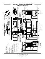
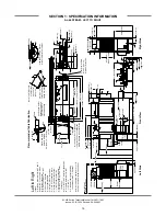
SECTION 1: SPECIFICATION INFORMATION

AJ-44 STEAM - LEFT TO RIGHT

9

Summary of Contents for AJ-44

Page 1: ... 1060 Barbourville KY 40906 606 523 9795 Fax 606 523 9196 www jacksonmsc com AJ 44 RACK CONVEYOR DISHMACHINE SERIES September 29 2007 P N 07610 001 76 22 Revision H AJ 44CE AJ 44CEL AJ 44CGP AJ 44CS AJ 44CSL AJ 66CE AJ 66CEL AJ 66CGP AJ 66CS AJ 66CSL AJ 80CE AJ 80CEL AJ 80CS AJ 80CSL ...

Page 2: ...on if serial number has been removed or altered or if unit is used for purpose other than it was origi nally intended TRAVEL LIMITATIONS Jackson MSC limits warranty travel time to 2 two hours and mileage to 100 one hundred miles Jackson MSC will not pay for travel time and mileage that exceeds this or any fees such as those for air or boat travel without prior authorization WARRANTY REGISTRATION C...

Page 3: ... PRODUCT FAILURE TO DO SO WILL VOID THE WARRANTY LLAME AL 1 888 800 5672 PARA REGISTRAR ESTE PRODUCTO AL NO HACERLO LA GARANTIA SERA ANULADA S V P APPELER 1 888 800 5672 POUR ENREGISTRER CE PRODUIT LA GARANTIE SERA ANNULEE POUR TOUT PRODUIT NON ENREGISTREE ...

Page 4: ...W 7600 Added Gas Exhaust Fan Schematic component kits H 03 21 2006 MAW 7571 7558 7634 Added themostat replacement kits Added vent cowl assembly for hooded side loader Replaced rinse drain weldment Added scrap basket strainer kit 98 04 19 2007 MAW 7898 Added 09905 003 32 20 fan load decal to the exhaust fan control kit Added warranty pages and service centers listings 35 36 05 03 2007 MAW 7913 Adde...

Page 5: ...lation Date Service Rep Name Phone No Jackson MSC LLC provides technical support for all of the dishmachines detailed in this manual We strongly recommend that you refer to this manual before making a call to our technical support staff Please have this manual with you when you call so that our staff can refer you if necessary to the prop er page Technical support is available from 8 00 a m to 5 0...

Page 6: ...Loader Right to Left Dimensions 24 Side Loader Installed Dimensions 25 D226 Steam Booster Dimensions 26 D226 Steam Booster Plumbing Line Drawings 27 Typical Electric and Gas Booster Dimensions 28 II INSTALLATION OPERATION INSTRUCTIONS Installation Instructions 30 Deliming Operations 33 Changing the AJ 44CE CS Direction of Travel 34 Curtain Installation Diagrams 40 Side Loader Installation Operatio...

Page 7: ...s 87 AJ 66 Drain Plumbing Assembly Left to Right CGP Models 88 AJ 66 Drain Plumbing Assembly Right to Left CGP Models 89 Drain Quench Assembly 90 Motor Assemblies 91 Prewash Wash Pump Weldments 92 Lower Wash Arm Assembly 93 Prewash Arm Upper Wash Arm Assembly 94 Curtains Tub Magnets 95 Final Rinse Assembly 96 Drive Assembly 97 Door Assemblies 99 Pawl Bar Miscellaneous Components 100 AJ 44 AJ 66 Pa...

Page 8: ... 50 60 Hz 3 Phase Secondary Side 142 380 460 600 Volt 60 Hz 3 Phase Primary Side 143 380 460 600 Volt 60 Hz 3 Phase Secondary Side 144 380 415 440 Volt 50 Hz 3 Phase Primary Side 145 380 415 440 Volt 50 Hz 3 Phase Secondary Side 146 AJ 66CS CSL AJ 80CS CSL 200 230 Volt 50 60 Hz 1 Phase Primary Side 147 200 230 Volt 50 60 Hz 1 Phase Secondary Side 148 200 230 Volt 50 60 Hz 3 Phase Primary Side 149 ...

Page 9: ...1 SECTION 1 SPECIFICATION INFORMATION ...

Page 10: ... WASH MINIMUM 160 F RINSE MINIMUM 180 F AJ 44 66 80CEL CSL MODELS PREWASH RECOMMENDED 110 140 F WASH MINIMUM 140 F RINSE MINIMUM 140 F FLOW PRESSURE PSI 20 5 FLOWRATE GPM AJ 44 66 80CE CS CGP 3 9 AJ 44 66 80CEL CSL 3 9 MINIMUM CHLORINE PPM AJ 44 66 80CEL CSL MODELS ONLY 50 STEAM COIL TANK HEAT CS CSL MODELS ONLY STEAM INLET PRESSURE PSIG 10 20 STEAM CONNECTION NPT 3 4 CONSUMPTION 15 PSIG lbs hr AJ...

Page 11: ...15 AMP 208 1 60 11 A 15 AMP 230 1 60 11 A 15 AMP 200 3 60 7 A 15 AMP 208 3 60 7 A 15 AMP 230 3 60 7 A 15 AMP 380 3 60 6 A 15 AMP 460 3 60 4 A 15 AMP 600 3 60 4 A 15 AMP AJ 66CE CEL MODELS TYPICAL TOTAL ELECTRICAL VOLTS PH HZ AMPS CIRCUIT 208 3 50 58 A 80 AMP 220 3 50 53 A 70 AMP 230 3 50 54 A 70 AMP 380 3 50 31 A 40 AMP 415 3 50 34 A 45 AMP 440 3 50 33 A 45 AMP 208 1 60 89 A 125 AMP 230 1 60 82 A ...

Page 12: ... A 20 AMP 230 3 60 13 A 20 AMP 380 3 60 13 A 20 AMP 460 3 60 7 A 15 AMP 600 3 60 8 A 15 AMP NOTE Always refer to the machine data plate for specific electrical and water requirements The material provided on this page is for reference only and may be subject to change without notice D226 STEAM BOOSTER ELECTRICAL REQUIREMENTS VOLTAGE V 200 230 FREQUENCY HZ 50 60 PHASE SINGLE WATER REQUIREMENTS INCO...

Page 13: ...5mm 25 635mm 10 254mm 7 178mm D E A C A B 18 1 2 467mm 25 635mm 4 1 2 114mm 4 102mm Table to Table Overall With Doors Open Rear of Machine Dish Clearance 14 356mm Minimum 10 High Table Backsplash Scrap Trough 7 1 2 190mm C B Legend A Machine water inlet 3 4 NPT 180 F Hi temp 140 F Low temp minimum B Electrical connection C Drain connection 1 1 2 NPT D Vent collar Optional E Vent cowl standard Note...

Page 14: ... 737mm 6 152mm 7 1 2 193mm 21 533mm 25 635mm 25 635mm 10 254mm 7 178mm D E A C A B 18 1 2 467mm 25 635mm 4 1 2 114mm 4 102mm Table to Table Overall With Doors Open Rear of Machine Dish Clearance 7 1 2 190mm C B Legend A Machine water inlet 3 4 NPT 180 F Hi temp 140 F Low temp minimum B Electrical connection C Drain connection 1 1 2 NPT D Vent collar Optional E Vent cowl standard Note All vertical ...

Page 15: ...ater inlet for gas booster heater H 3 4 NPT 180 F Water Outlet connection to line on dishmachine Connection hose provided by manufacturer J 3 4 NPT Gas Connection K 4 OD Vent pipe connection Flue to be installed to meet local codes by installing contractor Note All vertical dimensions are 1 2 from floor due to adjustable bullet feet 1 25mm K J H G 3 4 19 mm Table Turndown Flange 3 4 Max 21 533 mm ...

Page 16: ... 3 4 NPT 180 F Water Outlet connection to line on dishmachine Connection hose provided by manufacturer J 3 4 NPT Gas Connection K 4 OD Vent pipe connection Flue to be installed to meet local codes by installing contractor Note All vertical dimensions are 1 2 from floor due to adjustable bullet feet 60 1 4 1530mm 1 25mm 66 1 4 1684mm 4 102 mm wide x 16 406 mm long cutout in Vent Cowl Splash Shield ...

Page 17: ...nal E Vent cowl standard F 3 4 NPT Steam connection G 3 4 NPT Condensate return H Steam electrical connection J 1 NPT Steam connection K 3 4 Condensate connection L 3 4 NPT Incoming 110 F water connection M 3 4 NPT 180 F water to dishmachine Note All vertical dimensions are 1 2 from floor due to adjustable bullet feet 60 1 4 1530mm 8 204mm 7 178mm 10 254mm 12 1 2 316mm G F 17 1 2 445mm 4 102 mm wi...

Page 18: ...wl standard F 3 4 NPT Steam connection G 3 4 NPT Condensate return H Steam electrical connection J 1 NPT Steam connection K 3 4 Condensate connection L 3 4 NPT Incoming 110 F water connection M 3 4 NPT 180 F water to dishmachine Note All vertical dimensions are 1 2 from floor due to adjustable bullet feet 60 1 4 1530mm 8 204mm 7 178mm 10 254mm 12 1 2 316mm G F 17 1 2 445mm 4 102 mm wide x 16 406 m...

Page 19: ...t 3 4 NPT 180 F Hi temp 140 F Low temp minimum B Electrical connection C Drain connection 1 1 2 NPT D Vent collar Optional E Vent cowl standard F Prewash water inlet 3 4 NPT 110 F 140 F G Cold water thermostat plumbing connection 3 4 NPT Optional Note All vertical dimensions are 1 2 from floor due to adjustable bullet feet 82 2086mm 74 1883mm 44 1121mm 3 4 19 mm Table Turndown Flange 3 4 Max 21 53...

Page 20: ...067mm 41 1041mm 24 610mm 10 1 4 260mm F 24 610mm G 23 1 2 599mm 60 1 4 1530mm 66 1 4 1684mm Floor Sink Or Drain With 3 76 mm Minimum Drain Line 25 635mm 4 1 2 114mm 8 1 4 210mm 21 533mm B A F Table to Table Overall Prewash Plan View Section with Cold Water Thermostat 16 3 4 425mm 16 1 4 415mm F G 82 2086mm 74 1883mm 66 1679mm 3 4 19 mm Table Turndown Flange 3 4 Max 21 533 mm Rack Rail Height Above...

Page 21: ...tion C Drain connection 1 1 2 NPT D Vent collar Optional E Vent cowl standard F 3 4 NPT 180 F Water Inlet for wash tank fill final rinse tank heating From gas booster heater Interconnecting hose provided by manufacturer G 3 4 NPT 140 F Water inlet for gas booster heater H 3 4 NPT 180 F Water Outlet connection to line on dishmachine Connection hose provided by manufacturer J 3 4 NPT Gas Connection ...

Page 22: ...plash Shield Shipped with Cover Plate 22 559mm 44 1121mm Base Unit Prewash Left to Right Legend A Machine water inlet 3 4 NPT 180 F Hi temp 140 F Low temp minimum B Electrical connection C Drain connection 1 1 2 NPT D Vent collar Optional E Vent cowl standard F 3 4 NPT 180 F Water Inlet for wash tank fill final rinse tank heating From gas booster heater Interconnecting hose provided by manufacture...

Page 23: ...le and Lip of Machine to Prevent Leakage Recommended Table Fabrication Note Tub Will Accept a Table Flange Up to 24 7 8 632 mm Left to Right Legend A Machine water inlet 3 4 NPT 180 F Hi temp 140 F Low temp minimum B Electrical connection C Drain connection 1 1 2 NPT D Vent collar Optional E Vent cowl standard F 3 4 NPT Steam connection G 3 4 NPT Condensate return H Steam electrical connection J 1...

Page 24: ...0 1 4 260mm F 24 610mm G 23 1 2 599mm 60 1 4 1530mm 66 1 4 1684mm Floor Sink Or Drain With 3 76 mm Minimum Drain Line 25 635mm 4 1 2 114mm 8 1 4 210mm 21 533mm B A F Table to Table Overall Prewash Plan View Section with Cold Water Thermostat 16 3 4 425mm 16 1 4 415mm F G 82 2086mm 74 1883mm 66 1679mm 3 4 19 mm Table Turndown Flange 3 4 Max 21 533 mm Rack Rail Height Above Dishtable 1 4 6mm 5 16 8m...

Page 25: ... Optional Note All vertical dimensions are 1 2 from floor due to adjustable bullet feet 88 2238mm 44 1121mm 3 4 19 mm Table Turndown Flange 3 4 Max 21 533 mm Rack Rail Height Above Dishtable 1 4 6mm 5 16 8mm Rack Rail Tub Table Use Silicone Sealer Between Table and Lip of Machine to Prevent Leakage Recommended Table Fabrication Note Tub Will Accept a Table Flange Up to 24 7 8 632 mm 1 25mm 66 1 4 ...

Page 26: ...B A F Table to Table Overall Prewash Plan View Section with Cold Water Thermostat 16 3 4 425mm 16 1 4 415mm F G 88 2238mm 3 4 19 mm Table Turndown Flange 3 4 Max 21 533 mm Rack Rail Height Above Dishtable 1 4 6mm 5 16 8mm Rack Rail Tub Table Use Silicone Sealer Between Table and Lip of Machine to Prevent Leakage Recommended Table Fabrication Note Tub Will Accept a Table Flange Up to 24 7 8 632 mm ...

Page 27: ...rive Unit L 14 356mm Minimum 10 High Table Backsplash Scrap Trough Floor Sink Or Drain With 3 76 mm Minimum Drain Line Legend A Machine water inlet 3 4 NPT 180 F Hi temp 140 F Low temp minimum B Electrical connection C Drain connection 1 1 2 NPT D Vent collar Optional E Vent cowl standard F 3 4 NPT 180 F Water Inlet for wash tank fill final rinse tank heating From gas booster heater Interconnectin...

Page 28: ...Right Side 34 864mm 8 1 2 217mm 21 533mm 25 635mm 12 307mm 25 635mm B Dish Clearance 6 155mm J K G H 36 914mm 31 1 4 797mm 6 1 2 165mm 6 152mm 26 1 2 673mm Legend A Machine water inlet 3 4 NPT 180 F Hi temp 140 F Low temp minimum B Electrical connection C Drain connection 1 1 2 NPT D Vent collar Optional E Vent cowl standard F 3 4 NPT 180 F Water Inlet for wash tank fill final rinse tank heating F...

Page 29: ... D E C A B 41 1039mm 8 206mm G 24 610mm 23 1 2 600mm O 18 457mm 41 1043mm 4 102mm Drive Unit N 14 356mm Minimum 10 High Table Backsplash Scrap Trough Floor Sink Or Drain With 3 76 mm Minimum Drain Line 38 966mm 11 1 4 285mm 13 1 2 345mm 23 3 4 604mm 13 1 2 345mm 4 1 4 110mm 5 3 4 148mm 8 1 2 218mm 6 1 4 159mm M K L J F H 17 1 2 445mm 12 1 2 316mm F 16 3 8 417mm 15 3 4 400mm 11 5 8 295mm 6 3 8 162m...

Page 30: ... 75 1 2 1921mm 60 1 4 1529mm 62 3 4 1592mm 29 735mm 10 1 4 260mm 6 152mm 10 254mm G A B 41 1042mm C 23 1 2 598mm 24 611mm G 42 1069mm 4 102mm Drive Unit F D E 8 203mm 41 1041mm 38 965mm 7 178mm Right Side Legend A Machine water inlet 3 4 NPT 180 F Hi temp 140 F Low temp minimum B Electrical connection C Drain connection 1 1 2 NPT D Vent collar Optional E Vent cowl standard F Prewash water inlet 3 ...

Page 31: ...R DISHWASHER LENGTH 8 4 1 2 MINIMUM 25 DISHWASHER 5 12 1 2 14 1 2 29 1 1 2 TABLE ROLL 20 3 4 OPENING 1 A A 1 2 MINIMUM 1 2 DISHTABLE USE SILICONE BETWEEN TABLE AND LIP OF SIDE LOADER TO PREVENT LEAK AGE WALL OF SIDE LOADER SECTION A A CENTER LINE DISHMACHINE SPLASH SHIELD VENT CONNECTION OPENING 1 1 2 DRAIN CONNECTED TO DISHMACHINE DRAIN LINE CONVEYOR DISHMACHINE 15 on 30 model 30 on 30 model ...

Page 32: ...8 23 CONVEYOR DISHMACHINE LENGTH 4 1 2 MINIMUM 12 1 2 25 DISHWASHER 5 1 1 2 TABLE ROLL 20 3 4 OPENING 1 1 2 MINIMUM DISHTABLE 1 2 WALL OF SIDE LOADER USE SILICONE BETWEEN TABLE AND LIP OF SIDE LOADER TO PRE VENT LEAKAGE SECTION A A CONVEYOR DISHMACHINE CENTER LINE DISHMACHINE VENT CONNECTION OPENING SPLASH SHIELD A A 1 1 2 DRAIN CONNECTED TO DISHMACHINE DRAIN LINE 15 on 30 model 30 on 30 model ...

Page 33: ...ORMATION SIDE LOADER INSTALLED DIMENSIONS 25 Refer to chart above 34 23 or 30 10 4 23 SIDE LOADER DIMENSIONS 30 SIDE LOADER DIMENSIONS MODEL AJ 44 AJ 66 AJ 80 MODEL AJ 44 AJ 66 AJ 80 DIMENSIONS 75 97 111 DIMENSIONS 82 104 118 Left to Right installation shown for reference NOTE ALL DIMENSIONS ARE TYPICAL ...

Page 34: ...10 001 76 22 Issued 03 21 2006 Revised N A SECTION 1 SPECIFICATION INFORMATION D226 STEAM BOOSTER DIMENSIONS 26 16 6 16 16 13 11 NOTE All dimensions are in inches and are for reference only 43 11 24 14 4 43 11 14 4 24 11 16 16 13 6 16 ...

Page 35: ...nical Manual 7610 001 76 22 Issued 03 21 2006 Revised N A SECTION 1 SPECIFICATION INFORMATION D226 STEAM BOOSTER PLUMBING LINE DRAWINGS 27 Steam Booster Piping Double Tank Machine Steam Booster Piping Single Tank Machine ...

Page 36: ...ow 3 4 NPT Nipple 2 1 4 3 1 4 7 7 8 200 mm 18 457 mm 6 152 mm 6 152 mm 3 1 4 83 mm 36 914 mm PMG 200 RIGHT SIDE VIEW Water Outlet Water Inlet Gas Inlet Alternate Flue Location TPRV 4 102 mm Vent Adapter Water Outlet Water Inlet Gas Inlet Water Outlet Electrical Electrical Water Inlet Gas Inlet 36 914 mm PMG 200 LEFT SIDE VIEW Water Outlet Water Inlet Gas Inlet Alternate TPRV Location Electric Boos...

Page 37: ...29 SECTION 2 INSTALLATION OPERATION INSTRUCTIONS ...

Page 38: ... from the water line that may potentially get trapped in the valves or cause an obstruction Any valves that are fouled as a result of foreign matter left in the water line and any expenses resulting from this fouling are not the responsibility of the manufacturer Water hardness should be a maximum of 6 grains per gallon Harder water should be treated prior to using the machine Iron in the water su...

Page 39: ...machine operating requirements machine voltage total amperage load and serial number To install the incoming power lines open the control box Install conduit into the pre punched holes in the back of the control box Route power wires and connect to power block and grounding lug Install the service wires L1 L2 and L3 3 phase only to the appropriate terminals as they are marked on the terminal block...

Page 40: ...al of the bulkhead plug in the rear of the tub and replacing it with the third party detergent injection fitting Remove the bulkhead plug in the side of the tub to install the detergent concentration probe For more information concerning detergent concerns please refer to the page entitled Detergent Control The 1 8 brass plugs on the incoming plumbing rinse injector may be removed to install sanit...

Page 41: ...isconnect or turn off all chemical feeder pumps 3 Close all doors after adding the deliming solution 4 Run the machine for the recommended period of time 5 Turn the unit off and open the doors 6 Wait five minutes then inspect the inside of the machine If the machine is not delimed run another time cycle as per the deliming solution s instructions 7 When clean drain and re fill the machine 8 Run in...

Page 42: ...will be needed to perform this maintenance evolution 1 5 16 nutdriver 2 7 16 nutdriver 3 7 16 combination wrench 4 7 16 socket with drive ratchet and 4 extension 5 12 pipe wrench 6 10 adjustable wrench 7 Wire cutters 8 Phillipshead screwdriver TIME REQUIRED It is estimated that it will take 1 person three hours to perform this task not including all of the items indicated in the section entitled P...

Page 43: ... to hold the bolt head inside the control box Remove the locknuts from the opposite bolts used to hold down the control box do not remove the bolts and secure the bracket to underside of the hood The folded part of the brack et should be facing the rear of the machine Immediately tight en down the locknuts 5 Remove the splash shield which is bolted to the underside of the hood next to the wash man...

Page 44: ...eldment on the hood top 13 The rinse manifold must be removed This may prove dif ficult while the rinse injector is still mounted With great care it is possible to gently lift the rinse injector off of the hood to allow the rinse manifold to be removed from the unit Ensure that the gasket in the underside of the hood stays with the rinse manifold as it must be replaced when re installing the manif...

Page 45: ...h the wash drain barb in it Put the plumbing back together after ensuring that the rinse drain tee has been rotated Use thread tape to pro tect the threads while putting the plumbing back together Ensure that the wash drain barb is in the exact same position it was prior to this step 18 On the underside of the tub remove the rinse drain weld ment and the rinse drain plug Switch their locations so ...

Page 46: ...stalled Tighten down with the locknuts 27 Re install the rinse manifold with its gasket by connect ing it to the rinse injector weldment at its new location Remove the locknut from the stud for the bracket down near the rack rails and then secure the bracket to the machine using the same lock nut 28 Re install the lower wash arm support bracket to the pawl bar support on the end of the tub opposit...

Page 47: ...been replaced and none of the gaskets are torn or pinched as this could lead to leaking when the machine operates 35 Re install the heater box cover SPECIAL PARTS Gasket Rinse Injector Mfg No 05330 111 42 81 AFTER MAINTENANCE ACTIONS 1 Reconnect the incoming water and drain lines and then restore power to the unit Run the unit for at least 1 2 hour to ensure there are no leaks Test the unit with a...

Page 48: ...21 21 12 12 21 L L S S L R L HOODED SIDE LOADER UNHOODED SIDE LOADER UNHOODED SIDE LOADER HOODED SIDE LOADER ELECTRIC STEAM MACHINES L L S S L R L 66 12 S 80 S 12 L R S S L L 12 12 21 21 80 S 12 66 L R S S L 12 12 21 21 12 12 24 5 L S S XL R L 44 GAS MACHINES XL 24 5 24 5 XL 24 5 XL L 21 L 21 21 L R L 44 L R L S S L L 21 12 12 21 21 21 21 12 12 L L S S R L 21 21 12 12 21 Please refer to the chart ...

Page 49: ...sing and pre soaking are good ideas especially for silverware and casserole dishes Place cups and glasses upside down in racks so that they do not hold water during the cycle The dishmachine is meant not only to clean but to sanitize as well to destroy all of the bacteria that could be harmful to human beings In order to do this ware must be properly prepared prior to being placed in the machine W...

Page 50: ... is necessary to remove all foreign matter such as chips resulting from cutting or threading pipes pipe joint compound or if soldered fittings are used bits of solder or cuttings from the lines This debris if not removed may lodge in the valves and render them inoperative The D226 Booster is designed to take incoming water from a minimum temperature of 110 F to approximately 180 F for use in the f...

Page 51: ...n of the D226 Booster NOTE This explanation assumes that water and steam have been connected to the machine 1 When the power switch S1 is placed in the ON position power is provided to both the power light E1 and the thermostat TS1 2 The thermostat TS1 will close when the water falls below the minimum setpoint energizing the steam solenoid light E2 and the steam solenoid FS1 3 The steam solenoid F...

Page 52: ...nection on the other unit before cutting the hose Use a barbed hose fitting that is screwed onto the second connection to gauge the correct distance Ensure a smooth flow of hose without any sharp turns or kinks To aid in pushing the barbed hose fitting into the hose place the fitting on a hard surface i e the floor with the barbed end of the fitting pointing upward and push the hose down onto the ...

Page 53: ...O THE LEFT OF THE DISHMACHINE CONNECTION HOSES ARE CUT TO LENGTH DURING INSTALLATION ENOUGH HOSE IS PROVIDED TO LOCATE THE GAS BOOTER HEATER APPROXIMATELY 9 FEET AWAY FROM THE DISHMACHINE ADDITIONAL HOSE MUST BE ORDERED IF A GREATER DISTANCE IS REQUIRED DISTANCES GREATER THAN 20 FEET AWAY CAN AFFECT THE HEATING PERFORMANCE OF THE UNIT HOSES MARKED A IN THE ABOVE ILLUSTRATIONS CONNECT TO THE INLET ...

Page 54: ...lly for silverware and casserole dishes Place cups and glasses upside down in racks so that they do not hold water during the cycle The dishmachine is meant not only to clean but to sanitize as well to destroy all of the bacteria that could be harmful to human beings In order to do this ware must be properly prepared prior to being placed in the machine DAILY MACHINE PREPARATION Refer to the secti...

Page 55: ...EANING GAS HEATED MODELS At the end of the work day shut down the gas booster in accor dance with manufacturer s instructions Place the power switch in the OFF position secure the flow to the machine and open the door s Open the drain valves and allow the machine to drain completely Remove the pawl bar assembly clean as required Remove the pan strainers and if equipped the prewash strainers run of...

Page 56: ... box it is pos sible to change the sanitizing mode after the machine has left the original manufacturer s facility This change can only be performed by an authorized Jackson service technician If the machine does not have a dataplate like the one shown the sanitization mode CAN NOT be changed Follow the instructions below to change the mode of sanitiza tion Failure to follow these instructions can...

Page 57: ...mum rinse temperature Apply the correct sanitizing mode label in a visible location on the side of the control box INSTALL SANITIZER DISPENSER For machines in the chemical sanitizing mode a NSF Standard 29 approved chemical dispenser must be installed to dispense sanitizer into the final rinse line Follow instructions included with the chemical dispenser The system selected must be able to pro vid...

Page 58: ...for operators Using too much detergent has as detrimental effects as using too little The proper amount of detergent must be used for job It is important to remember that certain menu items may require extra detergent by their nature and personnel need to be made aware of this Experience in using the dishmachine under a variety of conditions along with good training in the operation of the machine...

Page 59: ... the switch 2 Parts of the table switch are mounted in the dishtable at the end of the table and under the table See the drawing s for the relationship of the switch to the table 3 Move the limit switch as far down on the two slots as possible and see that the limit switch is straight on the base plate This might require adjustment of the nut on the connector for the limit switch 4 Then adjust the...

Page 60: ...52 SECTION 3 PREVENTATIVE MAINTENANCE ...

Page 61: ...work harder and decreases efficiency Again it is important to remind operators that trying to perform corrective maintenance on the dishmachine could lead to larg er problems or even cause harm to the operator If a problem is discovered secure the dishmachine using proper shut down procedures as listed in this manual and contact Jackson Some problems however may having nothing to do with the machi...

Page 62: ... Turn the adjusting screw clockwise to increase pressure and counter clockwise to decrease Pressure can be read on the pressure gauge located on the water out let side of the heat exchanger Once the desired pressure is achieved tighten the top nut to ensure that the adjustment can not be accidently changed The water pressure regulator has an internal strainer that can be removed through the bottom...

Page 63: ...GMA 7 Gear Oil AGMA 8 Gear Oil AGMA 7 Gear Oil N A N A Castrol Tribol 800 220 Tribol 1105 7C Tribol 1105 8C Tribol 1105 7C Tribol 800 680 Tribol 800 460 Chevron Tegra 220 Cylinder Oil W460 Cylinder Oil W680 Cylinder Oil W460 Tegra 680 Tegra 460 Conoco Syncon R O Inca Oil 460 Inca Oil 680 Inca Oil 460 N A Syncon R O 220 460 Exxon Esso Teresstic SHP220 Spartan EP 460 Spartan EP 680 Spartan EP 460 Te...

Page 64: ...nge These oils are appropriate for any application but are especially useful when units are subjected to low start up temperatures or high operating temperatures However continuous operation above 225 F may cause dam age to seals or other components It is recommended that the initial oil be changed or filtered after the first 1500 hours of operation to remove metal particles that accumulate during...

Page 65: ...57 SECTION 4 TROUBLESHOOTING SECTION ...

Page 66: ...ressure Verify that incoming water pressure during fill is 20 5 PSI 2 Incoming water solenoid is clogged Verify that debris is not entrapped in valve If so remove debris Problem Low wash tank temperature 1 Low incoming water temperature Verify that the incoming water temperature matches what is indicated on the machine data plate 2 Heater not energizing Verify that the wash tank heater is operatin...

Page 67: ...Spotting of silverware glasses and dishes 1 Incorrect final rinse temperature Verify that the rinse water temperature matches that which is listed on the machine data plate 2 Clogged wash and or rinse nozzles and arms Remove the arms and verify that they and their nozzles are from debris 3 Excessively hard water Install a water softener to reduce hardness 4 Loss of water pressure due to clogged ob...

Page 68: ... Replace the heat exchanger Problem Solenoid valve is not opening shutting 1 Power not connected to the unit through the control box Open the control box cover and verify that incoming power lines are connected and light 2 Service breaker tripped or open Verify that the breaker is closed 3 Power switch connections could be loose Ensure that the connections are of sound quality 4 Power switch is fa...

Reviews: