C
Ri
ght Side
34 [864mm]
8
1
2
[217mm]
21 [533mm]
25 [635mm]
12 [307mm]
25 [635mm]
B
Dis
h Clearanc
e
Drive Unit
Left Si
de
66
1
2
[1692mm]
3 [79mm]
1
2
[
15mm]
84 [2134mm]
A
M
L
With Doors
Open
Rear of
M
a
ch
in
e
6 [152mm]
1 [25mm]
Drive Unit
Front View
75
1
2
[1919mm]
62
1
2
[1590mm]
29 [737mm]
6 [152mm]
10 [254mm]
C
A
B
4 [102mm]
7 [178mm]
D
E
8 [203mm]
42 [1067mm]
41 [1041mm]
24 [610mm]
10
1
4
[260mm]
L
24 [610mm]
M
23
1
2
[599mm]
60
1
4
[1530mm]
66
1
4
[1684mm]
F
loor Sink
Or Drain
With 3"
(76 mm)
Minimum Drain Line
25 [635mm]
4 1/2 [114mm]
8
1
4
[210mm]
21 [533mm]
B
A
L
T
able to T
able
Ov
erall
Prewas
h Plan View Sec
tion
wit
h Cold Wat
e
r Thermos
tat
16
3
4
[425mm]
16
1
4
[415mm]
F
G
82 [2086mm]
74 [1883mm]
66 [1679mm]
3/4"
(19 mm)
T
able T
u
rndown
F
lange 3/4"
Max
21"
(533 mm)
Rac
k
Rail Height
Abov
e Dis
htable
1/
4"
(6mm) - 5/
16"
(8mm)
Rac
k
Rail
Tu
b
T
able
Us
e Silic
one Sealer
Between T
able and
Lip of Mac
h
ine to
Prev
ent Leak
age
Recommended Table Fabr
ication
Not
e
: Tub Will A
c
c
ept
a T
able F
lange
Up to 24 7/8"
(632 mm)
4"
(102 mm) wide x
16"
(406 mm)
long c
u
tout in Vent Cowl/Splas
h
Shield. Shipped with Cov
e
r Plate.
22 [559mm]
44 [1121mm]
B
a
s
e
Unit
P
rewas
h
Left to Right
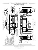
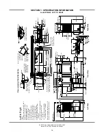
Legend
A - Mac
h
ine water inlet 3/4"
NPT
, 180°F
Hi-temp,140°
F
Low-temp minimum
B - Elec
tric
al c
onnec
tion
C - Drain c
onnec
tion 1-1/2"
NPT
D - Vent c
o
llar - Optional
E - Vent c
o
wl s
tandard
F
- 3/4"
NPT
180°
F
Water Inlet for was
h
tank
f
ill,
f
inal rins
e,
& t
ank
heat
ing.
From gas
boos
ter heater. Interc
onnec
ting hos
e
prov
ided by
manufac
turer.
G - 3/4"
NPT
140°
F
Water inlet for
gas
boos
ter heater.
H - 3/4"
NPT
180°
F
Water Outlet
c
onnec
tion to line on dis
h
mac
h
ine.
Connec
tion hos
e prov
ided by
manufac
turer.
J
- 3/4"
NPT
Gas
Connec
tion
K - 4"
OD Vent pipe c
onnec
tion. F
lue to
be ins
talled to meet loc
a
l c
odes
by
ins
talling c
ontrac
tor.
L - Prewas
h water inlet 3/4"
NPT
110°
F
-140°F
M - Cold water thermos
tat plumbing
c
onnec
tion 3/4"
NPT
- Optional
Not
e
: A
ll v
e
rt
ic
al dimens
ions
are +/- 1/2"
from
floor due to adjus
table bullet feet.
6 [152mm]
30 [763mm]
14 [357mm]
7
1
4
[185mm]
1
1
4
[
35mm]
K
J
H
G
K
J
H
G
8
3
4
[222mm]
11
3
4
[298mm]
14
3
4
[375mm]
20
3
4
[527mm]
36 [914mm]
26
1
2
[672mm]
31
1
4
[794mm]
6
1
2
[163mm]
16 [407mm]
AJ-44C Series Technical Manual 7610-001-76-22
Issued: 03-21-2006 Revised: 09-29-2007
SECTION 1: SPECIFICATION INFORMATION
AJ-66 GAS - RIGHT TO LEFT
14


