background image

16

07610-001-76-22-N

On 3-Phase machines only, correct pump motor rotation must be verified before 

the machine is operated.  Failure to do so can result in damage to the machine and 
components.
1.  Follow the Power Up section.

2.  Locate the wash pump motor and identify the arrow decal which shows the correct 

motor rotation (if no decal is present, correct rotation is toward front of machine).

3.  Flip AUTOMATIC/DELIME button to DELIME.
4.  Flip ON/OFF button to ON.

5. 

Observe rotation of motor fan and quickly flip ON/OFF button to OFF.

6.  If rotation is incorrect, disconnect electrical power and reverse the L1 and L2 

connections at terminal block shown in the previous section. 

The machine should be located with an adequate exhaust hood or ventilation system with 

provisions for venting. This is essential to permit efficient removal of the condensation ex

-

haust. Ensure the exhaust system is acceptable in accordance with applicable codes and 
standards.


Any damage caused by steam and/or moisture due to improper ventilation    

                    is NOT covered under the warranty.

Machine ventilation requirements:  

•  Load End: 200 CFM

•  Unload End: 400 CFM

The exhaust system must be sized to handle this volume for the machine to operate 
properly.

The thermostats on this machine have been set at the factory and should only be adjusted 
by an authorized service agent.

There are two Table Limit Switch options available.  Click on the instruction icons below for 
install guides.

 Striker 

Switch 

   Whisker 

Switch

INSTALLATION

INSTRUCTIONS

THERMOSTATS

VENTILATION

NOTICE

TABLE LIMIT

SWITCH OPTION


MOTOR 

ROTATION

i

CAUTION!

 On 

3-Phase machines 

only, correct pump 

motor rotation 

must be verified 

before operation!

!

CAUTION

RO

TA

TIO

N

Motor Fan

Summary of Contents for AJ-44

Page 1: ...AJ SERIES AJ 44 Series Manual 07610 001 76 22 N INSTALLATION OPERATION AND SERVICE MANUAL AJ SERIES CONVEYOR DISHMACHINES ...

Page 2: ...lled by Jackson at the factory and are shipped with the Dishmachine carry only a 1 one year parts warranty Labor to repair or replace these components is not included in the warranty or covered by Jackson Booster heaters not manufactured by Jackson are not covered by this warranty but are warranted by their respective manufacturers This warranty is void if any defect or failure is a direct result ...

Page 3: ...ROM DEFECTS IN MATERIALS AND WORKMANSHIP AND IS REPORTED TO JACKSON WITHIN 30 THIRTY DAYS FROM THE DATE OF INSTALLATION 9 DAMAGE CAUSED BY LABOR DISPUTE 10 DAMAGES RESULTING FROM IMPROPER CONNECTION TO UTILITY SERVICE 11 DAMAGES RESULTING FROM WATER CONDITIONS INADEQUATE OR EXCESSIVE WATER PRESSURE ACCIDENTS ALTERATIONS IMPROPER USE ABUSE HANDLING OVERLOADS TAMPERING IMPROPER INSTALLATION OR FAILU...

Page 4: ...instructions and all necessary information for change of sanitization mode 5 22 111 8 29 07 MAW N A Updated dimension pages Removed alternate table limit swithes I 10 9 09 KJS 8044 Changed part 05700 021 67 50 to 09515 003 58 12 J 1 16 14 MHH QOF NDB 219 Updated manufacturer information K 3 23 15 KAP N A Updated temperature on pgs 13 14 19 and 20 Updated pressure regulator information on pgs 30 an...

Page 5: ... this manual We strongly recommend that you refer to this manual before making a call to our technical support staff Please have this manual open when you call so that our staff can refer you if necessary to the proper page Technical support is not available on holidays Contact technical support toll free at 1 888 800 5672 Technical support is available for service personnel only ...

Page 6: ...g 13 Leveling 13 Facility Hot Water Heater 13 Plumbing 14 Drain Line 14 Electrical Power Connections 15 Motor Rotation 16 Ventilation 16 Thermostats 16 Table Limit Switch Option 16 Chemical Feeder Equipment 17 Connection Points 17 Exhaust Fan Timer 18 Curtains 19 Hose Installation 20 OPERATION Operating Instructions 21 Preparation 21 Power Up 21 First Rack 22 Ware Preparation 22 Washing a Rack of ...

Page 7: ...ssembly 44 Recirculating Pump 45 System Connections 46 AJ 44 Drain Plumbing 47 AJ 66 Drain Plumbing L R 48 AJ 66 Drain Plumbing R L 49 Solenoid Valve Vacuum Breaker 50 Drain Water Tempering Kit 51 Motor 52 Pre wash Wash Pumps 54 Pre wash Upper Wash Arm 55 Lower Wash Arm 56 Final Rinse 57 Doors 58 Drive Assembly 59 Pawl Bar Roller Bracket 61 Pawl Bars 62 AJ 44 Rack Rails 63 AJ 66 Rack Rails 64 Rins...

Page 8: ...s Parts 73 Go Box 75 SCHEMATICS AJ 44CGP 208 230 V 60 Hz 1 Phase 76 208 230 V 60 Hz 3 Phase 77 460 V 60 Hz 3 Phase 78 AJ 66CGP 208 230 V 60 Hz 1 Phase 79 208 230 V 60 Hz 3 Phase 80 380 460 600 V 60 Hz 3 Phase 81 Exhaust Fan 82 Side loader 83 ...

Page 9: ... i Caustic chemicals ABBREVIATIONS ACRONYMS ANSI American National Standards Institute CFM Cubic Feet per Minute FPM Feet per Minute GHT Garden Hose Thread GPM Gallons per Minute GPG Grains per Gallon HP Horse Power Hz Hertz ID Inside Diameter in lbs Inch Pounds kW Kilowatts NFPA National Fire Protection Association NPT National Pipe Thread PSI Pounds per Square Inch V Volts Instructions Hyperlink...

Page 10: ... 4 102 mm 8 203 mm 7 178 mm 18 467 mm 1 2 60 1530 mm 1 4 29 737 mm 10 254 mm B D E 6 152 mm C 7 178 mm 7 178 mm DRIVE KEY STROKE LEGEND A Water Inlet 3 4 NPT 110 140 F MIN B Electrical Connection C Drain Connection 1 1 2 NPT D Vent Collar Optional E Vent Cowl Standard F Water Inlet for Booster 3 4 NPT 110 140 F G Water Outlet to Machine 3 4 NPT 180 F H Gas Connection 3 4 NPT J Vent Pipe Connection...

Page 11: ...n 3 4 NPT J Vent Pipe Connection 4 OD All dimensions from the floor can be increased 1 using the machine s adjustable feet Items in red are not supplied with the machine 44 1118 mm Table to Table 52 1321 mm 62 1575 mm Overall 8 203 mm 21 535 mm B 14 355 mm MIN 4 102 mm x 16 406 mm Cut out in Vent Cowl Splash Shield Shipped with Cover Plate Scrap Trough 4 102 mm MIN 7 178 mm DRIVE KEY STROKE 75 191...

Page 12: ...m MIN 14 355 mm MIN B 75 1919 mm 1 2 62 1590 mm 1 2 4 102 mm 60 1530 mm 1 4 29 737 mm 10 254 mm B 6 152 mm 7 178 mm 7 178 mm DRIVE KEY STROKE LEGEND A Water Inlet 3 4 NPT 110 140 F MIN B Electrical Connection C Drain Connection 1 1 2 NPT D Vent Collar Optional E Vent Cowl Standard F Water Inlet for Booster 3 4 NPT 110 140 F G Water Outlet to Machine 3 4 NPT 180 F H Gas Connection 3 4 NPT J Vent Pi...

Page 13: ...nt Cowl Standard F Water Inlet for Booster 3 4 NPT 110 140 F G Water Outlet to Machine 3 4 NPT 180 F H Gas Connection 3 4 NPT J Vent Pipe Connection 4 OD K Pre wash Water Inlet 3 4 NPT 110 140 F L Cold Water Thermostat Optional 3 4 NPT All dimensions from the floor can be increased 1 using the machine s adjustable feet Items in red are not supplied with the machine K L D E C 8 203 mm 14 355 mm MIN...

Page 14: ... 1 4 29 737 mm 10 254 mm B 6 152 mm 7 178 mm 7 178 mm DRIVE KEY STROKE LEGEND A Water Inlet 3 4 NPT 110 140 F MIN B Electrical Connection C Drain Connection 1 1 2 NPT D Vent Collar Optional E Vent Cowl Standard F Water Inlet for Booster 3 4 NPT 110 140 F G Water Outlet to Machine 3 4 NPT 180 F H Gas Connection 3 4 NPT J Vent Pipe Connection 4 OD K Pre wash Water Inlet 3 4 NPT 110 140 F L Cold Wate...

Page 15: ...40 F G Water Outlet to Machine 3 4 NPT 180 F H Gas Connection 3 4 NPT J Vent Pipe Connection 4 OD K Pre wash Water Inlet 3 4 NPT 110 140 F L Cold Water Thermostat Optional 3 4 NPT All dimensions from the floor can be increased 1 using the machine s adjustable feet Items in red are not supplied with the machine 88 2238 mm 98 2489 mm Overall 80 2035 mm Table to Table K L D E C 8 203 mm 36 914 mm Pre...

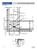
Page 16: ...the side loader 4 1 2 Minimum 25 Dishmachine 5 12 1 2 14 1 2 29 1 1 2 Table Roll 20 3 4 Opening 1 A A 1 2 Minimum 1 2 Dishtable Use silicone between table andlipof side loader to prevent leakage Wall of side loader Dishmachine Center line Splash Shield Vent Connection Opening 1 1 2 drain connected to dishmachine drain line Conveyor Dishmachine Section A A Left to Right ...

Page 17: ... Conveyor Dishmachine Dishmachine Center line Vent Connection Opening Splash Shield A A 1 1 2 drain connected to dishmachine drain line 14 1 2 29 8 or 15 depending on the width of the side loader 23 or 30 depending on the width of the side loader Conveyor Dishmachine Length 1 1 2 Table Roll 20 3 4 Opening 1 1 2 Minimum Dishtable 1 2 Wallofside loader Use silicone between table and lip of side load...

Page 18: ...6 AJ 80 DIMENSIONS 75 97 111 DIMENSIONS 82 104 118 Left to Right shown Depending on the width of the side loader 34 864 mm 4 102 mm 21 533 mm Rack Rail Height above Table 1 4 6 mm 5 16 8 mm Table Use Silicone Sealer between Table and Lip of Machine to Prevent Leaks Tub Rack Rail 3 4 19 mm Table Turndown Flange 3 4 19 mm MAX Tub Will Accept a Table Flange up to 24 7 8 632 mm Side loader Install Tab...

Page 19: ... Gallons per Rack AJ 44 66 80 0 94 Motor Characteristics Drive Motor HP 1 4 Wash Motor HP 2 Pre wash Motor AJ 66 HP 1 Pre wash Motor AJ 80 HP 2 WATER REQUIREMENTS AJ 44 66 80 Minimum Wash Temperature F C 150 66 Minimum Power Rinse Temperature F C 160 71 Minimum Rinse Temperature F C 180 82 Pre wash Temperature F C 110 140 43 60 Flow Pressure PSI 20 5 Flow Rate GPM 3 9 Water Line Size NPT 3 4 Drain...

Page 20: ...vailable Electrical Characteristics i SPECIFICATIONS ELECTRICAL REQUIREMENTS AJ 44CGP Volts Phase Freq Wash Motor Drive Motor Recirculating Pump Total Load MCA MOP 208 1 60 Hz 8 7 A 1 8 A 1 7 A 12 2 A 14 4 A 20 A 230 1 60 Hz 9 6 A 1 8 A 1 7 A 13 1 A 15 5 A 25 A 208 3 60 Hz 5 8 A 1 2 A 1 7 A 8 7 A 10 2 A 15 A 230 3 60 Hz 5 7 A 1 1 A 1 7 A 8 5 A 9 9 A 15 A 460 3 60 Hz 2 9 A 0 6 A 1 7 A 5 1 A 5 8 A 1...

Page 21: ...rom the pallet before installing Remove the wooden lift beams and their associated brackets after the machine has been positioned Open the front door and remove all materials from inside Once unpacked verify there are no missing parts If a part is missing contact the manufacturer immediately The machine is designed to operate while level This is important to prevent any damage to the machine durin...

Page 22: ...ssure occurs when there is no flow and the valves are closed Flow pressure occurs when water is running into the machine The water supply line must be 3 4 NPT minimum and must be able to provide water at the minimum temperature indicated on the machine data plate A shut off valve not supplied should be installed to isolate the machine from the water system in the event service is required An optio...

Page 23: ... power and ground wires to lugs as indicated by the appropriate decals in the control box Use copper conductors only Use of an anti oxidation agent is recommended on the power connections 5 Tighten all connections 6 Verify the incoming voltage matches the voltage indicated on the decal next to the incoming power pre punched hole The machine has a separate power connection for gas boosters and the ...

Page 24: ...em with provisions for venting This is essential to permit efficient removal of the condensation ex haust Ensure the exhaust system is acceptable in accordance with applicable codes and standards Any damage caused by steam and or moisture due to improper ventilation is NOT covered under the warranty Machine ventilation requirements Load End 200 CFM Unload End 400 CFM The exhaust system must be siz...

Page 25: ...pensers must be set for the type and concentration of chemicals being used Detergent usage and water hardness are two factors that contribute greatly to how efficiently the machine will operate Using the proper amount of detergent can be a source of substantial savings A qualified water treatment specialist can explain what is needed to gain the maximum efficiency from detergent WARNING Some chemi...

Page 26: ...220 100 110 120 130 140 150 160 170 180 190 200 210 220 L1 L2 L3 1 GRND TB3 TB2 1 4 7 A 3 6 9 B 1 4 7 A 3 6 9 B 1 4 7 A 3 6 9 B 1 4 7 A 3 6 9 B 1 4 7 A 3 6 9 B WASH RELAY LINE VOLTAGE DET L2 DET L1 CONVEYOR RELAY LINE VOLTAGE CVS L2 CVS L1 100 110 120 130 140 150 160 170 180 190 200 210 220 100 110 120 130 140 150 160 170 180 190 200 210 220 TB3 TB2 1 4 7 A 3 6 9 B 1 4 7 A WASH RELAY LINE VOLTAGE ...

Page 27: ...re missing they MUST be obtained and installed before operation INSTALLATION CURTAINS 21 12 12 21 L S L R L 64 S 12 12 12 12 S L R S S L 12 12 21 S 12 L R L S S L 21 12 12 21 12 S 86 100 S 12 21 12 12 L S S R L 12 S 86 100 S 12 12 12 S S R L 12 S S 12 12 S 64 L R S S 12 12 CGP XL 24 5 24 5 XL 24 5 XL XL 24 5 S 12 21 12 12 21 L S S R L 12 S S 12 12 S L R L S S L 21 12 12 21 Unhooded Side loader Hoo...

Page 28: ...booster ensuring there are no sharp turns or kinks 4 Cut hose even with yellow plastic stop on second barbed hose fitting 5 Push cut end of hose onto second barbed hose fitting until it meets yellow plastic stop A lubricant e g petroleum jelly can be used to aid in pushing hose onto fittings Connection Hose Attach hose fitting to this connection before making cut at other end of hose Barbed Hose F...

Page 29: ...d and steam is flowing to the machine 100 110 120 130 140 150 160 170 180 190 200 210 220 100 110 120 130 140 150 160 170 180 190 200 210 220 100 110 120 130 140 150 160 170 180 190 200 210 220 1 GRND TB3 TB2 1 4 7 A 3 6 9 B 1 4 7 A 3 6 9 B 1 4 7 A 3 6 9 B 1 4 7 A 3 6 9 B 1 4 7 A 3 6 9 B WASH RELAY LINE VOLTAGE DET L2 DET L1 CONVEYOR RELAY LINE VOLTAGE CVS L2 CVS L1 OPERATION OPERATING INSTRUCTION...

Page 30: ...re that is placed in a rack Materials should not be placed in the machine unless they are properly secured in a dish rack To start the cycle gently push the rack into the machine on the load end Once the wash actuator has moved sufficiently the machine will automatically begin to convey the dish rack through the machine The entire cycle is automatic Operators should periodically review the followi...

Page 31: ...apped in nozzles or deposited onto ware 1 Remove all strainers and use a hand scraper to scrape foodsoil into trash 2 Remove float switch cover and clean it and strainers with the pre rinse hose 3 Rinse float switch off and rinse the tank out Inspect tank for debris 4 Remove curtains scrub with mild detergent and brush and allow to air dry OPERATION OPERATING INSTRUCTIONS SHUTDOWN CLEANING For mac...

Page 32: ...er f Replace end caps and ensure they have been tightened g Replace wash arm manifolds The outside of the machine should be cleaned with a standard countertop or general cleaner Do not attempt to clean inside any compartments boxes or chambers that are secured with a cover These normally contain live electrical components CLEANING Do NOT clean the machine with any type of metallic scrubbing sponge...

Page 33: ...empty rack through the machine twice 10 Drain and re fill the machine 11 Reconnect turn on chemical feeder equipment CAUTION This equipment is not recommended for use with deionized water or other aggressive fluids Use of deionized water or other aggressive fluids will result in corrosion and failure of materials and components Use of deionized water or other aggressive fluids will void the manufa...

Page 34: ...en cleaning out strainers do NOT beat them on waste cans Wipe out strainers with a rag and rinse under a faucet if necessary Use a toothpick to dislodge any stubborn debris 3 Ensure all wash and rinse arms are secure in the machine before operating 4 Ensure drains are closed before operating 5 Remove as much soil from dishes by hand as possible before loading into racks 6 Do not overfill racks 7 E...

Page 35: ... 7 5 10 15 20 25 30 40 50 60 80 100 910 0 153 0 137 0 133 0 122 0 116 0 132 0 121 0 115 913 0 282 0 231 0 189 0 183 0 179 0 171 0 165 0 178 0 169 0 164 0 161 917 0 402 0 303 0 229 0 201 0 193 0 180 0 172 0 189 0 176 0 170 0 166 0 161 0 133 920 0 311 0 347 0 263 0 225 0 216 0 202 0 191 0 215 0 200 0 188 0 182 0 164 0 161 924 0 388 0 412 0 312 0 261 0 256 0 236 0 223 0 249 0 231 0 216 0 210 0 201 0 ...

Page 36: ...ours operation if machines are operating in a clean environment This can be extended to 10 000 hours if using new reformulated Mobil SHC lubricants orange in color and the lubricant remains free of contamination over this period See comments under Subsequent oil changes for discussion of severe ambient conditions Long term storage or infrequent operation If a speed reducer is to stand idle for an ...

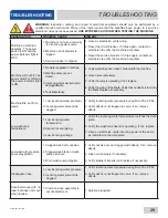
Page 37: ...essure during fill is 20 5 PSI 2 Verify debris is not trapped in valve If so remove debris Low wash tank temperature 1 Low incoming water temperature 2 Heater not energizing 3 Low incoming voltage 1 Verify the incoming water temperature matches the data plate 2 Verify the wash tank heater is operating If not replace 3 Have an electrician verify incoming power is the same as indicated on the data p...

Page 38: ...hes that on the machine data plate 8 Verify the drains are shut and the water level is correct Spotting of silverware glasses and dishes 1 Incorrect final rinse temperature 2 Clogged wash and or rinse nozzles and arms 3 Excessively hard water 4 Loss of water pressure due to clogged obstructed wash pump 5 Ware not being properly pre scrapped 6 Incorrect detergent chemical concentrations 1 Verify th...

Page 39: ... 111 44 45 8 1 Din Rail 05700 021 72 75 9 3 Screw 10 32 x 1 2 Phillips Trusshead 05305 011 39 36 10 1 Washer Flat 1 4 05311 174 01 00 11 1 Decal Ground 09905 011 86 86 12 1 Terminal Board 05940 002 78 97 100 110 120 130 140 150 160 170 180 190 200 210 220 100 110 120 130 140 150 160 170 180 190 200 210 220 L1 L2 L3 1 GRND TB3 TB2 1 4 7 A 3 6 9 B 1 4 7 A 3 6 9 B 1 4 7 A 3 6 9 B WASH RELAY LINE VOLT...

Page 40: ... 1 Fuse Holder 460 V Only 05920 011 72 89 22 1 Fuse 460 V Only 05920 011 72 88 23 10 Screw 6 32 x 3 8 Phillips Trusshead 05305 171 02 00 24 3 Control Relay 2 pole 05945 111 35 19 25 1 Wash Thermometer Decal Wash 06685 111 87 13 09905 002 97 61 26 1 Rinse Thermometer Decal Rinse 06685 111 68 49 09905 002 97 62 27 1 Decal Gauge 09905 021 82 65 ITEMS NOT SHOWN Grommet 1 2 OD x 3 8 ID 05325 011 46 73 ...

Page 41: ...ard 05940 002 78 97 13a 13b 13c 1 1 1 Drive Motor Contactor Wash Pump Motor Contactor Recirculating Rinse Pump Motor Contactor 05945 111 68 38 05945 111 68 38 05945 111 68 38 14 1 Circuit Breaker 208 230 V 60 Hz Models Only 05925 011 68 34 15 1 Recirculating Rinse Pump Motor Overload See Motor Overloads page 100 110 120 130 140 150 160 170 180 190 200 210 220 100 110 120 130 140 150 160 170 180 19...

Page 42: ...al Board 05940 021 89 41 19 1 Transformer 05950 002 46 10 20 4 Locknut 10 24 with Nylon Insert 05310 373 01 00 21 1 Fuse Holder 460 V Only 05920 011 72 89 22 1 Fuse 460 V Only 05920 011 72 88 23 12 Screw 6 32 x 3 8 Phillips Trusshead 05305 171 02 00 24 4 Control Relay 2 pole 05945 111 35 19 25 1 Relay 3 pole 05945 111 72 51 26 1 Rinse Thermometer 96 L R R L Decal Rinse 06685 111 68 49 09905 002 97...

Page 43: ...1 68 39 N A 05945 111 68 40 05945 111 68 40 460 60 3 05945 111 69 12 N A 05945 111 68 41 05945 111 68 41 AJ 66 VOLTS Hz PHASE DRIVE MOTOR PRE WASH MOTOR WASH MOTOR POWER RINSE MOTOR 208 60 1 N A N A N A N A 230 60 1 N A N A N A N A 208 60 3 05945 111 68 39 05945 111 68 41 05945 111 68 40 05945 111 68 40 230 60 3 05945 111 68 39 05945 111 68 41 05945 111 68 40 05945 111 68 40 460 60 3 05945 111 69 ...

Page 44: ...rame Weldment AJ 44 Frame Weldment AJ 66 L R Frame Weldment AJ 66 R L 05700 002 52 70 05700 002 49 28 05700 002 57 57 2 1 Front Dress Panel AJ 44 Front Dress Panel AJ 66 L R Front Dress Panel AJ 66 R L 05700 002 52 77 05700 002 51 22 05700 002 57 84 3 4 Adjustable Foot 05340 011 71 74 ...

Page 45: ...estor 1 2 06685 100 05 00 Tee 3 4 x 3 4 x 1 2 04730 211 06 00 Nipple 3 4 Close Brass 04730 207 34 00 SHOCK ABSORBER WATER ARRESTOR OPTION WATER TREATMENT OPTION Replacement Cartridge inspect at least every 6 months RSC 100 Scaltrol System 04730 003 05 76 ...

Page 46: ...00 011 67 99 05330 111 42 81 2 1 Nipple 3 4 x 6 05700 001 26 74 3 2 Elbow 90 degree Brass 3 4 04730 206 04 34 4 1 Vacuum Breaker 3 4 04820 002 53 77 5 1 Valve Solenoid 3 4 04730 100 53 00 6 2 Nipple Brass Close 3 4 04730 207 34 00 7 1 Y strainer 3 4 04730 717 02 06 6 5 5 4 1 2 3 7 Complete Pre wash Plumbing Assembly 05700 031 74 83 ...

Page 47: ...07610 001 76 22 N 39 2 1 3 4 5 6 7 8 19 10 21 14 11 12 18 6 12 13 11 17 8 22 20 9 15 6 7 4 3 5 16 18 PARTS PLUMBING Complete Plumbing Assembly 05700 002 51 17 ...

Page 48: ...30 411 46 01 11 2 Tee Copper 3 4 x 3 4 x 1 2 04730 411 03 01 12 2 Fitting Adapter 1 2 to 1 4 04730 401 41 01 13 1 Plug 1 4 Brass 04730 209 01 00 14 1 Valve Ball 1 4 04810 011 72 67 15 1 1 Gauge Pressure 0 100 PSI Decal 15 25 PSI 06685 111 88 34 09905 002 97 74 16 1 Nipple Brass 3 4 x 6 05700 001 26 74 17 1 1 Injector Fill Line Gasket Injector 05700 011 67 99 05330 111 42 81 18 1 Tube Copper 3 4 x ...

Page 49: ... 51 53 4 1 Bracket Plumbing Support 05700 002 50 70 5 1 Valve Solenoid 3 4 04810 100 53 00 6 1 Incoming Piping Assembly 05700 002 51 15 7 2 Bracket Inlet Plumbing Mounting 05700 002 51 41 8 2 Clamp Pipe 05700 000 35 06 9 1 Elbow 90 degree Brass 3 4 04730 206 13 00 1 2 2 3 4 5 6 7 8 2 9 PARTS RINSE HEADER PLUMBING Complete Rinse Header Plumbing Assembly 05700 002 51 16 ...

Page 50: ...0 2 2 Stand A 05700 002 74 82 3 1 Stand C 05700 002 74 84 4 4 Coil Gasket 05700 001 17 86 5 2 Flat Washer 05700 001 17 87 6 2 Coil Nut 05310 011 17 85 ITEM QTY DESCRIPTION PART NUMBER 1 1 Coil 05700 031 88 30 2 3 Stand A 05700 002 74 82 3 4 Coil Gasket 05700 001 17 86 4 2 Flat Washer 05700 001 17 87 5 2 Coil Nut 05310 011 17 85 Complete Coil Assembly L R 05700 041 88 31 Complete Coil Assembly R L ...

Page 51: ...0 002 48 50 ITEM QTY DESCRIPTION PART NUMBER 1 1 Thermostat High Limit 05930 011 49 43 2 1 Gasket 05330 200 02 70 3 1 Terminal Board 05940 002 78 97 4 1 Thermostat Bracket 05700 011 81 64 5 1 Decal Thermostat Regulating 09905 011 84 31 6 1 Thermostat Wash Regulating 06401 140 00 32 7 1 Fitting Brass 1 4 05310 924 02 05 Items Not Shown ...

Page 52: ...k Rinse 05700 002 45 05 4 1 Bracket Upper Rinse Tank 05700 002 67 13 5 1 Bracket Lower Rinse Tank 05700 002 67 14 6 1 Nipple 3 4 x 4 04730 207 05 00 7 3 Elbow 90 degree Brass 3 4 04730 206 13 00 8 1 Nipple Brass 3 4 04730 207 34 00 PARTS TANK ASSEMBLY 1 4 7 3 6 7 8 5 7 1 2 Bottom Angled View Top Angled View Complete Tank Assembly 05700 002 45 05 ...

Page 53: ...3 4 04730 206 13 00 3 1 Pump Recirculating Pump Recirculating Modified Pump Recirculating with Adapters 06105 002 05 26 05700 002 81 22 05700 002 51 28 4 1 Bracket Mounting AJ 66 L R 05700 002 25 74 5 1 Bracket Mounting All Other Models 05700 004 61 85 1 1 2 2 3 4 5 Complete Recirculating Pump Assembly 05700 002 51 29 Does not include bracket ...

Page 54: ...2 52 75 05700 002 51 38 C Hose Wash Coil Assembly 05700 002 52 76 04720 011 94 10 D Hose Wash Fill Supply 05700 003 03 97 05700 003 03 99 E Connection Hose to Gas Booster Outlet F Connection Hose to Gas Booster Inlet G Hose Coil Recirculating 05700 002 17 71 05700 002 17 71 Kit Gas Booster Connection 18 of Hose Four 3 4 Fittings 05700 002 51 73 05700 002 51 73 Each hose assembly includes two 3 4 f...

Page 55: ...Shown 05700 021 84 74 05700 002 87 05 3 1 Elbow 90 degree Street Brass 1 1 2 04730 206 32 00 4 1 Nipple Brass 1 1 2 04730 207 40 00 5 1 Cross Connector 1 1 2 04710 004 43 65 6 1 Fitting Barbed 1 1 2 x 1 1 2 04730 011 69 92 7 1 Rinse Nipple 05700 021 84 61 PARTS AJ 44 DRAIN PLUMBING Complete AJ 44 Drain Plumbing Assembly 05700 002 52 71 ...

Page 56: ...0 011 73 77 7 2 Tube Copper 1 1 2 x 1 3 4 See note below 8 1 Nipple Rinse 05700 021 84 61 9 2 Tube Copper 1 1 2 x 3 1 2 See note below 10 2 Tube Copper 1 1 2 x 7 1 2 See note below 11 1 Nipple Brass 1 1 2 x 3 04730 011 87 04 12 2 2 Handle Ball Valve Spacer Not Shown 05700 021 84 74 05700 002 87 05 Copper tubing should be purchased locally and cut to the length shown in the part description NOTICE ...

Page 57: ...Copper 1 1 2 x 8 1 8 See note below 9 2 Elbow Brass 90 degree 1 1 2 04730 011 73 77 10 3 Connector No hub 1 1 2 04720 003 73 73 11 1 Nipple Brass 1 1 2 x 3 04730 011 87 04 12 1 Nipple Rinse 05700 021 84 61 13 1 1 Handle Ball Valve Spacer Not Shown 05700 021 84 74 05700 002 87 05 14 1 1 Handle Ball Valve Long Spacer Not Shown 05700 002 57 83 05700 002 87 05 Copper tubing should be purchased locally...

Page 58: ...ve Body Complete 240 Volt Solenoid Valve Assembly 04810 100 03 18 Coil Housing only 06401 003 07 44 Complete Vacuum Breaker Assembly 04820 002 53 77 Components of Repair Kit 06401 003 06 24 Cap Screw Data Plate Cap O Ring Plunger Body Cap Retainer Spring Plunger 06401 003 07 40 O ring Diaphragm 06401 003 07 42 Complete 110 V Valve Assembly 3 4 04810 100 53 00 Coil Housing Only 04810 200 01 18 Comp...

Page 59: ...ng drain attach the two additional Tees Item 7 using the 1 1 2 Close Brass Nipples Item 8 Tighten the Reducers Items 6 and 9 into the Tees as shown above Attach the Modified Compression Fitting Item 10 into the 1 1 2 to 1 4 Reducer Item 9 Position the bulb of the thermostat Item 1 so that it rests approximately 1 4 from the bottom of the Tee Item 7 Tighten the Modified Compression Fitting Item 10 ...

Page 60: ... 45 05700 031 67 45 05700 031 71 78 6 1 Impeller Washer 05700 011 71 95 7 1 Bolt Hex Head 1 4 20 x 3 4 05305 004 42 64 8 1 Upper Support Bracket 05700 021 73 68 9 1 Nut 1 4 20 Serrated 05310 011 66 49 10 1 Lower Support Bracket 05700 021 73 71 11 1 Motor Mounting Gasket 05330 011 71 62 12 4 Cap Screw 3 8 16 x 2 05305 011 74 98 13 1 Motor Mounting Clamp 4 1 8 to 7 Not Shown 04730 002 32 15 1 2 3 4 ...

Page 61: ...6401 003 09 97 208 230 3 60 06105 121 70 58 06401 003 09 98 460 3 60 06105 121 70 58 06401 003 09 98 WASH MOTORS Volts Phase Hz Motor Part Number Complete Kit Part Number 208 230 1 60 06105 121 70 55 06401 003 10 40 200 230 3 60 06105 121 70 56 06401 003 10 38 460 3 60 06105 121 70 56 06401 003 10 38 PRE WASH MOTORS AJ 66 ...

Page 62: ...dment AJ 80 05700 031 81 47 5 1 Wash Pump Weldment All Models 05700 041 68 88 6 1 Pre wash Pump Weldment AJ 66 80 L R 05700 002 10 62 7 1 Pre wash Pump Weldment AJ 66 80 R L 05700 002 11 96 1 2 3 6 7 4 5 8 Nut Hex 3 8 16 05310 276 01 00 9 Washer Flat 3 8 05311 176 01 00 10 Lockwasher Split 3 8 05311 276 01 00 Pump weldments are secured to pump plates with the following not shown Parts are not show...

Page 63: ...10 32 x 3 8 05305 173 12 00 5 4 Lanyard 05340 011 72 46 6 1 Upper Wash Arm 05700 031 67 34 7 1 Cap Wash Tube 05700 021 69 68 8 2 O ring Upper Wash Arm 05330 011 74 56 9 3 O ring Pre wash Manifold 05330 400 12 08 10 1 Upper Wash Manifold Support Bracket Not Shown 05700 021 73 97 When replacing the screws in the end caps use a thread locking product to ensure the mounting screws do not come loose du...

Page 64: ...340 011 72 46 5 6 Mounting Screw End cap 10 32 x 3 8 05305 173 12 00 6 1 Bracket Lower Wash Arm Support Not Shown 05700 011 71 20 7 2 Locknut 1 4 20 with Nylon Insert Not Shown 05310 374 01 00 1 2 3 4 Complete Lower Wash Arm Assembly 05700 031 74 66 When replacing the screws in the end caps use a thread locking product to ensure the mounting screws do not come loose during operation NOTICE Kit con...

Page 65: ... 7 1 Rinse Pan Strainer 05700 041 85 09 8 2 Locknut 1 4 20 with Nylon Insert 05310 374 01 00 9 1 Rinse Drain Control Plate 05700 011 68 70 10 1 Rinse Drain Overflow Plate 05700 002 53 62 11 1 Left Rinse Pan Locator Bracket 05700 021 92 38 12 1 Rinse Tray 05700 002 51 18 13 1 Right Rinse Pan Locator Bracket 05700 021 92 37 141 1 Lower Rinse Arm Kit 06401 003 10 09 15 2 O ring 05330 011 74 55 16 2 R...

Page 66: ...172 09 00 4 1 Door Switch Magnet 05700 111 51 68 5 2 Door Glide 05700 111 70 92 6 3 Door Stop 05700 002 05 46 7 4 Locknut 10 24 Hex with Nylon Insert 05310 373 01 00 8 1 1 Left Door Guide Right Door Guide 05700 002 32 51 05700 031 76 44 9 1 Door Catch 05700 031 84 80 10 1 1 Door Hood Support Pre wash Door Hood Support 05700 031 84 13 05700 031 84 14 11 1 Door Stiffener Not Shown 05700 031 83 43 12...

Page 67: ...e Motor 05700 031 73 56 2 1 Drive Plate and Rod 05700 021 67 44 3 1 Adjuster Handle 05700 021 72 28 4 2 Coupling Expansion Legs 05700 021 67 50 5 1 Adjuster Crank Assembly 05700 021 69 95 6 1 Adjuster Scotch Yoke 05700 021 69 76 7 12 Lockwasher 3 8 05311 276 01 00 8 8 Flat Washer 3 8 05311 176 01 00 9 2 Block Pillow 03120 021 71 87 36 37 38 ...

Page 68: ...n Insert 05310 374 01 00 21 1 Spring Drive 05315 011 83 51 22 1 Hub Drive 05700 011 67 97 23 1 Set Screw 1 4 20 x 1 2 Not Shown 05305 011 71 51 24 3 Flat Washer 1 2 05311 011 71 93 25 1 Bolt 1 2 13 x 1 3 4 05305 011 71 94 26 1 Plate Drive Rod 05700 021 67 42 27 1 Bolt 10 32 x 3 8 Hex Head 05306 011 62 45 28 2 Nut Hex 1 4 20 05310 274 01 00 29 1 Socket Drive 05700 021 67 39 30 1 Plate Spacer 05700 ...

Page 69: ...84 68 4 1 1 Top Guide Block Guide Block Kit 05700 011 69 49 06401 003 10 15 5 1 Pawl Bar Gutter Gasket 05330 011 68 55 6 1 Bottom Guide Block 05700 011 69 50 7 1 Pawl Bar Gutter Kit 06401 003 09 95 Kit contains part s and all hardware When replacing one guide block the other guide block and the gasket should be replaced as well NOTICE 1 2 3 4 5 7 6 Parts are not shown to scale with relation to eac...

Page 70: ...401 241 81 06 L R 06401 341 81 06 Prison ITEM QTY DESCRIPTION PART NUMBER 1 12 on AJ 44 18 on AJ 66 20 on AJ 80 Rack Catch 09515 021 69 00 2 24 on AJ 44 36 on AJ 66 40 on AJ 80 Pawl Bar Spacer 05700 011 71 45 3 1 Pawl Bar AJ 44 05700 031 72 77 4 1 Pawl Bar AJ 66 05700 031 72 78 5 1 Pawl Bar AJ 80 05700 031 74 19 3 4 5 1 2 NOTICE When replacing rack catches ensure to re install in the appropriate d...

Page 71: ...700 031 67 59 05700 031 69 48 2 3 Actuator Switch Actuator Switch Replacement Kit1 05700 021 72 39 06401 003 10 14 3 6 Bolt Hex Head 1 4 20 x 3 4 05305 004 42 64 4 6 Pawl Bar Spacer 05700 011 71 44 5 6 Locknut 1 4 20 Hex with Nylon Insert 05310 374 01 00 1 2 3 4 5 1 Kit contains the switch two spacers and hardware ...

Page 72: ...64 07610 001 76 22 N PARTS AJ 66 RACK RAILS Left to Right Right to Left 1 4 2 3 4 5 6 7 1 ...

Page 73: ...6401 003 10 86 2 8 per rail Bolt Hex Head 1 4 20 x 3 4 05305 004 42 64 3 8 per rail Locknut 1 4 20 Hex with Nylon Insert 05310 374 01 00 4 3 per rail Actuator Switch Actuator Switch Replacement Kit1 05700 021 72 39 06401 003 10 14 5 8 per rail Pawl Bar Spacer 05700 011 71 44 6 1 Rack Rail L R Opposite Rack Rail L R 05700 031 76 27 05700 041 71 37 7 1 Rack Rail R L Opposite Rack Rail R L 05700 031 ...

Page 74: ...o 3 4 04730 011 65 14 6 1 Elbow 90 Degree Street Brass 1 04730 002 11 99 7 1 Nipple Brass 1 x 6 04730 002 12 00 8 1 Elbow 90 Degree Brass Female 04730 002 12 55 9 4 Lockwasher 1 4 05311 274 01 00 10 4 Bolt 1 4 20 x 1 2 05305 274 02 00 11 4 Nut Hex 1 4 20 05310 274 01 00 12 1 Rinse Motor Mounting Bracket Rinse Motor Mounting Bracket AJX 66 L R Only 05700 002 38 90 05700 002 39 33 8 7 6 11 5 10 9 2 ...

Page 75: ...1 85 11 3 1 Overflow Strainer Support 05700 001 96 48 4 1 Drain Guard Strainer 05700 002 09 15 5 1 Wash Intake Strainer 05700 002 51 52 6 1 Tub Strainer 05700 002 03 21 7 1 Screen Strainer with Handle 05700 002 09 04 8 1 Wash Strainer Separator 05700 031 84 38 1 2 3 4 5 6 7 8 Parts are not shown to scale with relation to each other ...

Page 76: ... Not Shown Locknut 1 4 20 with Nylon Insert Not Shown 05700 031 71 13 05311 174 01 00 05310 374 01 00 3 1 Shoulder Bolt Wingnut 05700 002 46 02 4 1 Fill Tube Wash Fill Tube Pre wash AJ 66 80 Gasket Fill Tube Not Shown Locknut 1 4 20 with Nylon Insert Not Shown 05700 021 71 21 05700 021 74 76 05330 111 42 81 05310 374 01 00 1 2 3 4 Parts are not shown to scale with relation to each other ...

Page 77: ...1 75 71 3 1 Wash Tank Float Switch Kit Pre wash Tank Float Switch Kit 06401 003 11 75 06401 003 11 76 4 1 Scrap Basket Lid 05700 002 56 55 5 1 Scrap Basket Assembly 06401 011 87 78 1 2 3 4 5 Kit contains part s and all hardware When installing float switch kit washer goes inside tub and nut goes outside tub NOTICE Parts are not shown to scale with relation to each other ...

Page 78: ...Limit Switch Bracket 05700 021 71 18 8 1 Conveyor Switch Kit 06401 003 11 79 9 1 Middle Curtain Hook 05700 011 72 65 10 1 Curtain Hook 05700 011 83 54 11 1 Curtain Rod 05700 003 77 52 12 1 Curtain XL Side loader Not Shown 08415 003 84 88 13 1 Curtain Rod Side loader Not Shown 05700 003 84 57 S 12 L 21 XL 24 5 1 2 3 4 5 6 7 8 10 11 9 Kit contains the switch a terminal and a wire nut Cut the cord on...

Page 79: ...07610 001 76 22 N 71 PARTS SIDE LOADER PARTS 1 2 3 5 6 4 7 8 9 10 11 12 13 14 15 16 Parts are not shown to scale with relation to each other ...

Page 80: ...er 05340 108 01 03 5 1 Leg Socket Kit 06401 003 09 79 6 1 Leg Support Kit 06401 003 09 80 7 1 Vent Cowl Assembly for Hooded Side loader 05700 003 15 66 8 1 Pawl Bar Roller Bracket 05700 031 77 94 9 1 Pawl Bar Gutter Kit 06401 003 09 95 10 1 Rack Catch 05700 021 86 79 11 1 Front Strainer Side loader 05700 021 85 10 12 1 Drive Linkage Kit L R 06401 003 11 59 13 1 Drive Linkage Kit R L 06401 003 11 6...

Page 81: ... Scoop Option 05700 002 04 08 6 1 Delay Timer Exhaust Fan 05945 004 22 78 7 1 Terminal Board Exhaust Fan 05940 011 84 41 8 1 Din Rail Exhaust Fan 05700 002 36 09 9 1 Decal Exhaust Fan Load 09905 003 32 20 10 1 Striker Plate Limit Switch Complete Assembly 05700 002 62 94 11 1 Whisker Plate Limit Switch Complete Assembly 05700 002 06 83 Kit contains part s and all hardware Parts are not shown to sca...

Page 82: ...1 71 39 4 1 Splash Shield 05700 031 85 16 5 1 Hole Direction Plate Kit 06401 003 10 00 6 1 Rinse Drain Plate Gasket 05330 011 72 27 7 1 Pipe Clamp 05700 000 35 05 8 1 Rinse Drain Plate Kit 06401 003 10 07 9 1 Rinse Drain Plug Kit 06401 003 10 06 10 1 Rinse Drain Weldment Kit 06401 003 10 05 1 2 3 4 5 6 7 8 9 10 Kit contains part s and all hardware Parts are not shown to scale with relation to each...

Page 83: ...111 51 68 2 O ring Pre wash Manifold 05330 400 12 08 2 O ring Wash Manifold 05330 011 74 56 1 Overload Drive Motor 05945 111 68 39 1 Overload Wash Motor 05945 111 68 40 1 Relay 120 V 3 PDT 05945 111 72 51 1 Relay 120 V 50 60 Hz 3A Control 05945 111 35 19 1 Repair Kit Vacuum Breaker 3 4 04820 001 60 57 4 Roller Pawl Bar 05700 011 68 16 1 Kit Seal for Wash and Pre wash Pump 05330 011 71 98 2 Solenoi...

Page 84: ...76 07610 001 76 22 N SCHEMATICS AJ 44CGP 208 230 V 60 HZ 1 PHASE AJ 44CGP SCHEMATIC ...

Page 85: ...07610 001 76 22 N 77 SCHEMATICS AJ 44CGP 208 230 V 60 HZ 3 PHASE AJ 44CGP SCHEMATIC ...

Page 86: ...78 07610 001 76 22 N SCHEMATICS AJ 44CGP 460 V 60 HZ 3 PHASE AJ 44CGP SCHEMATIC ...

Page 87: ...07610 001 76 22 N 79 SCHEMATICS AJ 66CGP 208 230 V 60 HZ 1 PHASE AJ 66CGP SCHEMATIC ...

Page 88: ...80 07610 001 76 22 N SCHEMATICS AJ 66CGP 208 230 V 60 HZ 3 PHASE AJ 66CGP SCHEMATIC ...

Page 89: ...07610 001 76 22 N 81 SCHEMATICS AJ 66CGP 380 460 600 V 60 HZ 3 PHASE AJ 66CGP SCHEMATIC ...

Page 90: ...ED YEL TO R10 6 66 GRY BLU BLK WHT TO TB2 LEGEND T TB TERMINAL BOARD TIMER GAS CONVEYOR EXHAUST FAN HOOKUP 9905 003 14 58a TO R8 6 44 TO R14 6 86 TO R10 9 66 TO R8 9 44 TO R14 9 86 TO TB2 GRY TB L1 L2 CUSTOMER PROVIDED FAN CONTACTOR COIL CUSTOMER SUPPLIED VOLTAGE MAX 250V ...

Page 91: ...07610 001 76 22 N 83 SCHEMATICS SIDE LOADER ...

Page 92: ...Jackson WWS Inc 6209 N US Hwy 25E Gray KY 40734 USA 1 888 800 5672 www jacksonwws com AJ 44 Series Manual 07610 001 76 22 N ...

Reviews: