background image

AJX-44 & AJX-54 Series Technical Manual 7610-003-60-98

Issued: 01-19-2009  Revised: 01-30-2009

SECTION 5: PARTS SECTION

MISCELLANEOUS PARTS AND WELDMENTS

74

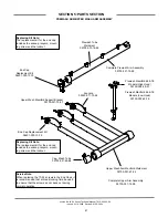
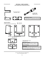
Run Off Sheet Weldment

05700-021-71-39

Plate, Right Water

Directional

05700-021-79-23

Plate, Left Water

Directional

05700-021-79-27

Splash Shield Weldment

05700-031-85-16

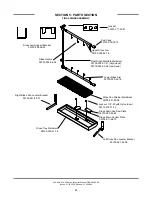
Hole Direction Plate Replacment Kit

06401-003-10-00

Replacment Kit Note:

The kit for the hole direction plate comes

with  the  plate,  a  new  gasket  and  the

mounting hardware.

Pipe Clamp

05700-000-35-05

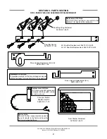
Rinse Drain Plate Replacment

Kit

(TG Models Only)

06401-003-10-07

Rinse Drain Weldment Replacement Kit 

06401-003-10-05

Rinse Drain Plate Gasket

05330-011-72-27

Replacement Kits Notes:

The  kits  for  the  drain  weldments  and

drain 

plugs 

come 

with 

the

weldments/parts, a new gasket and the

mounting hardware.

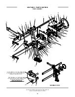
Prewash Fill Tube Weldment

(AJX-66, 76, 80 & 90 Models Only)

05700-021-74-76

Vellumoid Gasket

05330-111-42-81

Shoulder Bolt Wingnut Weldment

05700-002-46-02

Summary of Contents for AJX-44 Series

Page 1: ...m AJX 44 AJX 54 SERIES RACK CONVEYOR DISHMACHINE October 13 2014 P N 7610 003 60 98 Revision J AJX 44 SERIES AJX 44CE AJX 44CS AJX 54 SERIES AJX 54CE AJX 54CS AJX 66 SERIES AJX 66CE AJX 66CS AJX 76 SERIES AJX 76CE AJX 76CS AJX 80 SERIES AJX 80CE AJX 66CS AJX 90 SERIES AJX 90CE AJX 90CS AND ASSOCIATED OPTION PACKAGES INCLUDING SIDE LOADER ...

Page 2: ...ion if serial number has been removed or altered or if unit is used for purpose other than it was origi nally intended TRAVEL LIMITATIONS Jackson WWS limits warranty travel time to 2 two hours and mileage to 100 one hundred miles Jackson WWS will not pay for travel time and mileage that exceeds this or any fees such as those for air or boat travel without prior authorization WARRANTY REGISTRATION ...

Page 3: ...PRODUCT FAILURE TO DO SO WILL VOID THE WARRANTY LLAME AL 1 888 800 5672 PARA REGISTRAR ESTE PRODUCTO AL NO HACERLO LA GARANTIA SERA ANULADA S V P APPELER 1 888 800 5672 POUR ENREGISTRER CE PRODUIT LA GARANTIE SERA ANNULEE POUR TOUT PRODUIT NON ENREGISTREE ...

Page 4: ...ent 05700 021 67 50 to a cast ing 09515 003 58 12 E 12 01 2009 ARL 091125 1404 CW Changed a dimension on page 30 the dimension between the mounting holes was indicated as 2 00 but should have been 2 88 F 10 29 2010 RLC 101029 1336 CW Updated Print for mounting Table Limit Switch G 05 09 2012 RLC QOF 386 Added chart for cut lengths on 66 76 80 90 L R drain plumb ing H 03 19 2013 RLC QOF NDB 219 Upd...

Page 5: ... support for all of the dishmachines detailed in this manual We strongly recommend that you refer to this manual before making a call to our technical support staff Please have this manual with you when you call so that our staff can refer you if necessary to the prop er page Technical support is available from 8 00 a m to 5 00 p m EST Monday through Friday Technical support is not available on ho...

Page 6: ...llation Instructions 21 Deliming Operations 24 Curtain Installation Diagrams 25 Side Loader Installation Operation Instructions 26 Dishmachine Operating Instructions 27 Detergent Control 29 Striker Plate Limit Switch Installation Instructions 30 III PREVENTATIVE MAINTENANCE General Maintenance 32 Lubrication Chart for Drive Gear 33 Drive Motor Gear Reducer Preventative Maintenance 34 IV TROUBLESHO...

Page 7: ...kets 76 Curtains Tub Magnets 77 Vent Cowl Assembly Vent Scoop Option 78 Exhaust Fan Control Limit Switch Options 79 SIDE LOADER SECTION Side Loader Track Assembly Leg Replacements 80 Side Loader Pawl Bar Assemblies Strainer Magnet 81 Side Loader Pawl Bar Associated Parts 82 Side Loader Vent Cowl Option 83 Rinse Fill Option 84 VI ELECTRICAL SCHEMATICS AJX 44CE AJX 54CE 208 230 Volt 50 60 Hz 1 Phase...

Page 8: ...1 SECTION 1 SPECIFICATION INFORMATION ...

Page 9: ...44 66 80 54 76 90 High Temp 6 2 AJX 44 66 80 54 76 90 Low Temp 5 75 GALLONS PER RACK AJX 44 66 80 54 76 90 High Temp 69 AJX 44 66 80 54 76 90 Low Temp 79 WATER TEMPERATURES AJX 44 66 80 54 76 90 MODELS PREWASH RECOMMENDED AJX 66 76 80 90 110 140 F WASH MINIMUM 160 F RINSE MINIMUM 180 F FLOW PRESSURE PSI 15 FLOWRATE GPM AJX 44 66 80 54 76 90 High Temp 2 57 AJX 44 66 80 54 76 90 Low Temp 2 74 STEAM ...

Page 10: ...3 60 N A 12 3 A 20 AMP AJX 80CS 230 3 60 N A 12 3 A 20 AMP AJX 80CS 460 3 60 N A 6 2 A 15 AMP AJX 44 AJX 54 Series Technical Manual 7610 003 60 98 Issued 01 19 2009 Revised 01 30 2009 SECTION 1 SPECIFICATION INFORMATION ELECTRICAL REQUIREMENTS 3 NOTE Typical Electrical Circuit is based upon 1 125 of the full amperage load of the machine and 2 typical fixed trip cir cuit breaker sizes as listed in ...

Page 11: ...60 N A 105 3 A 150 AMP AJX 90CE 230 1 60 N A 97 1 A 125 AMP AJX 90CE 208 3 60 N A 62 3 A 80 AMP AJX 90CE 230 3 60 N A 57 5 A 80 AMP AJX 90CE 460 3 60 N A 28 8 A 40 AMP AJX 90CS 208 1 60 N A 18 8 A 25 AMP AJX 90CS 230 1 60 N A 18 8 A 25 AMP AJX 90CS 208 3 60 N A 12 3 A 20 AMP AJX 90CS 230 3 60 N A 12 3 A 20 AMP AJX 90CS 460 3 60 N A 6 2 A 15 AMP AMPS CIRCUIT 82 4 A 125 AMP 75 5 A 100 AMP 48 4 A 60 ...

Page 12: ...25 635mm 10 254mm 7 178mm D E A C A B 18 1 2 467mm 25 635mm 4 1 2 114mm 4 102mm Table to Table Overall With Doors Open Rear of Machine Dish Clearance 14 356mm Minimum 10 High Table Backsplash Scrap Trough 7 1 2 190mm C B Legend A Machine water inlet 3 4 NPT 180 F Hi temp 140 F Low temp minimum B Electrical connection C Drain connection 1 1 2 NPT D Vent collar Optional E Vent cowl standard Note All...

Page 13: ...mm 6 152mm 7 1 2 193mm 21 533mm 25 635mm 25 635mm 10 254mm 7 178mm D E A C A B 18 1 2 467mm 25 635mm 4 1 2 114mm 4 102mm Table to Table Overall With Doors Open Rear of Machine Dish Clearance 7 1 2 190mm C B Legend A Machine water inlet 3 4 NPT 180 F Hi temp 140 F Low temp minimum B Electrical connection C Drain connection 1 1 2 NPT D Vent collar Optional E Vent cowl standard Note All vertical dime...

Page 14: ...E Vent cowl standard F 3 4 NPT Steam connection G 3 4 NPT Condensate return H Steam electrical connection J 1 NPT Steam connection K 3 4 Condensate connection L 3 4 NPT Incoming 110 F water connection M 3 4 NPT 180 F water to dishmachine Note All vertical dimensions are 1 2 from floor due to adjustable bullet feet 60 1 4 1530mm 8 204mm 7 178mm 10 254mm 12 1 2 316mm G F 17 1 2 445mm 4 102 mm wide x...

Page 15: ...tandard F 3 4 NPT Steam connection G 3 4 NPT Condensate return H Steam electrical connection J 1 NPT Steam connection K 3 4 Condensate connection L 3 4 NPT Incoming 110 F water connection M 3 4 NPT 180 F water to dishmachine Note All vertical dimensions are 1 2 from floor due to adjustable bullet feet 60 1 4 1530mm 8 204mm 7 178mm 10 254mm 12 1 2 316mm G F 17 1 2 445mm 4 102 mm wide x 16 406 mm lo...

Page 16: ...4 NPT 180 F Hi temp 140 F Low temp minimum B Electrical connection C Drain connection 1 1 2 NPT D Vent collar Optional E Vent cowl standard F Prewash water inlet 3 4 NPT 110 F 140 F G Cold water thermostat plumbing connection 3 4 NPT Optional Note All vertical dimensions are 1 2 from floor due to adjustable bullet feet 82 2086mm 74 1883mm 44 1121mm 3 4 19 mm Table Turndown Flange 3 4 Max 21 533 mm...

Page 17: ...m 41 1041mm 24 610mm 10 1 4 260mm F 24 610mm G 23 1 2 599mm 60 1 4 1530mm 66 1 4 1684mm Floor Sink Or Drain With 3 76 mm Minimum Drain Line 25 635mm 4 1 2 114mm 8 1 4 210mm 21 533mm B A F Table to Table Overall Prewash Plan View Section with Cold Water Thermostat 16 3 4 425mm 16 1 4 415mm F G 82 2086mm 74 1883mm 66 1679mm 3 4 19 mm Table Turndown Flange 3 4 Max 21 533 mm Rack Rail Height Above Dis...

Page 18: ...nd Lip of Machine to Prevent Leakage Recommended Table Fabrication Note Tub Will Accept a Table Flange Up to 24 7 8 632 mm Left to Right Legend A Machine water inlet 3 4 NPT 180 F Hi temp 140 F Low temp minimum B Electrical connection C Drain connection 1 1 2 NPT D Vent collar Optional E Vent cowl standard F 3 4 NPT Steam connection G 3 4 NPT Condensate return H Steam electrical connection J 1 NPT...

Page 19: ...4 260mm F 24 610mm G 23 1 2 599mm 60 1 4 1530mm 66 1 4 1684mm Floor Sink Or Drain With 3 76 mm Minimum Drain Line 25 635mm 4 1 2 114mm 8 1 4 210mm 21 533mm B A F Table to Table Overall Prewash Plan View Section with Cold Water Thermostat 16 3 4 425mm 16 1 4 415mm F G 82 2086mm 74 1883mm 66 1679mm 3 4 19 mm Table Turndown Flange 3 4 Max 21 533 mm Rack Rail Height Above Dishtable 1 4 6mm 5 16 8mm Ra...

Page 20: ...ional Note All vertical dimensions are 1 2 from floor due to adjustable bullet feet 88 2238mm 44 1121mm 3 4 19 mm Table Turndown Flange 3 4 Max 21 533 mm Rack Rail Height Above Dishtable 1 4 6mm 5 16 8mm Rack Rail Tub Table Use Silicone Sealer Between Table and Lip of Machine to Prevent Leakage Recommended Table Fabrication Note Tub Will Accept a Table Flange Up to 24 7 8 632 mm 1 25mm 66 1 4 1684...

Page 21: ...F Table to Table Overall Prewash Plan View Section with Cold Water Thermostat 16 3 4 425mm 16 1 4 415mm F G 88 2238mm 3 4 19 mm Table Turndown Flange 3 4 Max 21 533 mm Rack Rail Height Above Dishtable 1 4 6mm 5 16 8mm Rack Rail Tub Table Use Silicone Sealer Between Table and Lip of Machine to Prevent Leakage Recommended Table Fabrication Note Tub Will Accept a Table Flange Up to 24 7 8 632 mm 4 10...

Page 22: ... C A B 41 1039mm 8 206mm G 24 610mm 23 1 2 600mm O 18 457mm 41 1043mm 4 102mm Drive Unit N 14 356mm Minimum 10 High Table Backsplash Scrap Trough Floor Sink Or Drain With 3 76 mm Minimum Drain Line 38 966mm 11 1 4 285mm 13 1 2 345mm 23 3 4 604mm 13 1 2 345mm 4 1 4 110mm 5 3 4 148mm 8 1 2 218mm 6 1 4 159mm M K L J F H 17 1 2 445mm 12 1 2 316mm F 16 3 8 417mm 15 3 4 400mm 11 5 8 295mm 6 3 8 162mm M ...

Page 23: ...1 2 1921mm 60 1 4 1529mm 62 3 4 1592mm 29 735mm 10 1 4 260mm 6 152mm 10 254mm G A B 41 1042mm C 23 1 2 598mm 24 611mm G 42 1069mm 4 102mm Drive Unit F D E 8 203mm 41 1041mm 38 965mm 7 178mm Right Side Legend A Machine water inlet 3 4 NPT 180 F Hi temp 140 F Low temp minimum B Electrical connection C Drain connection 1 1 2 NPT D Vent collar Optional E Vent cowl standard F Prewash water inlet 3 4 NP...

Page 24: ...he side loader CONVEYOR DISHWASHER LENGTH 8 or 15 depending on the width of the side loader 4 1 2 MINIMUM 25 DISHWASHER 5 12 1 2 14 1 2 29 1 1 2 TABLE ROLL 20 3 4 OPENING 1 A A 1 2 MINIMUM 1 2 DISHTABLE USE SILICONE BETWEEN TABLE AND LIP OF SIDE LOADER TO PREVENT LEAK AGE WALL OF SIDE LOADER SECTION A A CENTER LINE DISHMACHINE SPLASH SHIELD VENT CONNECTION OPENING 1 1 2 DRAIN CONNECTED TO DISHMACH...

Page 25: ...idth of the side loader 23 or 30 depending on the width of the side loader CONVEYOR DISHMACHINE LENGTH 4 1 2 MINIMUM 12 1 2 25 DISHWASHER 5 1 1 2 TABLE ROLL 20 3 4 OPENING 1 1 2 MINIMUM DISHTABLE 1 2 WALL OF SIDE LOADER USE SILICONE BETWEEN TABLE AND LIP OF SIDE LOADER TO PRE VENT LEAKAGE SECTION A A CONVEYOR DISHMACHINE CENTER LINE DISHMACHINE VENT CONNECTION OPENING SPLASH SHIELD A A 1 1 2 DRAIN...

Page 26: ...r to chart above 34 23 or 30 depending on the width of the side loader 10 4 23 SIDE LOADER DIMENSIONS 30 SIDE LOADER DIMENSIONS MODEL AJX 44 AJX 66 AJX 80 AJX 54 AJX 76 AJX 90 MODEL AJX 44 AJX 66 AJX 80 AJX 54 AJX 66 AJX 80 DIMENSIONS 75 97 111 85 107 121 DIMENSIONS 82 104 118 92 114 128 Left to Right installation shown for reference NOTE ALL DIMENSIONS ARE TYPICAL ...

Page 27: ...20 SECTION 2 INSTALLATION OPERATION INSTRUCTIONS ...

Page 28: ... are fouled as a result of foreign matter left in the water line and any expenses resulting from this fouling are not the responsibility of the manufacturer Water hardness should be a maximum of 6 grains per gallon Harder water should be treated prior to using the machine Iron in the water supply can cause staining A filter designed to remove iron from the supply water is highly recommended for su...

Page 29: ...l power connections VOLTAGE CHECK Ensure that the power switch is in the OFF position and apply power to the dishmachine Check the incom ing power at the terminal block and ensure it corresponds to the voltage listed on the data plate If not contact a qualified service agency to examine the problem Do not run the dishmachine if the voltage is too high or too low Shut off the service breaker and ma...

Page 30: ...ating Terminals in the control box marked DET provide a voltage signal whenever the wash motor is operating DELIMING OPERATIONS In order to maintain the dishmachine at its optimum performance level it will be required to remove lime and corrosion deposits on a frequent basis A delim ing solution should be available from your detergent supplier Read and follow all instructions on the label of the d...

Page 31: ... Turn the unit off and open the doors 6 Wait five minutes then inspect the inside of the machine If the machine is not delimed run another time cycle as per the deliming solution s instructions 7 When clean drain and re fill the machine 8 Run in MANUAL for 10 minutes to remove residual deliming solution 9 Drain and re fill the machine This equipment is not recommend for use with deionized water or...

Page 32: ... S 12 L R S 12 L 21 S 12 XL 24 5 XL 24 5 R L R L L R S 12 XL 24 5 L 21 S 12 XL 24 5 S 12 S 12 S 12 S 12 XL 24 5 XL 24 5 L 21 44 54 L R 44 54 R L 66 76 80 90 L R 66 76 80 90 R L Please refer to the chart for placement of the curtains NOTE When machine is a Low Hood replace XL curtains with L curtains PART NUMBERS XL 08415 002 47 37 L 08415 131 73 45 S 08415 131 73 44 Curtain Rod 05700 021 73 43 ...

Page 33: ...ly throwing unscraped dishes into the machine simply defeats the purpose altogether of washing the ware Scraps should be removed from ware prior to being loaded into a rack Pre rinsing and pre soaking are good ideas especially for silverware and casserole dishes Place cups and glasses upside down in racks so that they do not hold water during the cycle The dishmachine is meant not only to clean bu...

Page 34: ...lly for silverware and casserole dishes Place cups and glasses upside down in racks so that they do not hold water during the cycle The dishmachine is meant not only to clean but to sanitize as well to destroy all of the bacteria that could be harmful to human beings In order to do this ware must be properly prepared prior to being placed in the machine DAILY MACHINE PREPARATION Refer to the secti...

Page 35: ...he drain valves and allow the machine to drain completely Remove the pawl bar assembly clean as required Remove the pan strainers and if equipped the prewash strain ers run off sheets and scrap basket strainer Remove the wash and if equipped the prewash arms and verify that the nozzles and arms are free from obstructions Flush the arms with fresh water Remove the pump suction strainers and clean o...

Page 36: ...rators Using too much detergent has as detrimental effects as using too little The proper amount of detergent must be used for job It is important to remember that certain menu items may require extra detergent by their nature and personnel need to be made aware of this Experience in using the dishmachine under a variety of conditions along with good training in the operation of the machine can go...

Page 37: ...he switch 2 Parts of the table switch are mounted in the dishtable at the end of the table and under the table See the drawing s for the relationship of the switch to the table 3 Move the limit switch as far down on the two slots as possible and see that the limit switch is straight on the base plate This might require adjustment of the nut on the connector for the limit switch 4 Then adjust the i...

Page 38: ...31 SECTION 3 PREVENTATIVE MAINTENANCE ...

Page 39: ...rder and decreases efficiency Again it is important to remind operators that trying to perform corrective maintenance on the dishmachine could lead to larg er problems or even cause harm to the operator If a problem is discovered secure the dishmachine using proper shut down procedures as listed in this manual and contact Jackson Some problems however may having nothing to do with the machine itse...

Page 40: ... 90W AGMA 7 Gear Oil AGMA 8 Gear Oil AGMA 7 Gear Oil N A N A Castrol Tribol 800 220 Tribol 1105 7C Tribol 1105 8C Tribol 1105 7C Tribol 800 680 Tribol 800 460 Chevron Tegra 220 Cylinder Oil W460 Cylinder Oil W680 Cylinder Oil W460 Tegra 680 Tegra 460 Conoco Syncon R O Inca Oil 460 Inca Oil 680 Inca Oil 460 N A Syncon R O 220 460 Exxon Esso Teresstic SHP220 Spartan EP 460 Spartan EP 680 Spartan EP ...

Page 41: ...ntinuous operation above 225 F may cause damage to seals or other components It is recommended that the initial oil be changed or filtered after the first 1500 hours of operation to remove metal particles that accumulate during break in Subsequent oil changes should be made after 5000 hours operation if units are operating in a clean environment This can be extended to 10 000 hours if using new re...

Page 42: ...35 SECTION 4 TROUBLESHOOTING SECTION ...

Page 43: ...re Verify that incoming water pressure during fill is 15 PSI 2 Incoming water solenoid is clogged Verify that debris is not entrapped in valve If so remove debris Problem Low wash tank temperature 1 Low incoming water temperature Verify that the incoming water temperature matches what is indicated on the machine data plate 2 Heater not energizing Verify that the wash tank heater is operating If no...

Page 44: ...g of silverware glasses and dishes 1 Incorrect final rinse temperature Verify that the rinse water temperature matches that which is listed on the machine data plate 2 Clogged wash and or rinse nozzles and arms Remove the arms and verify that they and their nozzles are from debris 3 Excessively hard water Install a water softener to reduce hardness 4 Loss of water pressure due to clogged obstructe...

Page 45: ...38 SECTION 5 PARTS SECTION ...

Page 46: ...al Manual 7610 003 60 98 Issued 01 19 2009 Revised 01 30 2009 SECTION 5 PARTS SECTION AJX 44 AJX 54 CONTROL BOX ASSEMBLY 39 1 2 4 5 4 8 9 10 11 12 13 14 15 10 16 17 17 4 18 19 20 21 22 21 22 21 22 22 23 24 25 26 22 27 22 28 7 6 3 ...

Page 47: ...ctor 05945 111 68 38 18 1 Heater Contactor 05700 002 24 70 19 1 Overload See Page 48 20 1 Overload See Page 48 21 1 Control Relay 05945 111 35 19 21 2 Control Relay 05945 111 72 51 22 10 Screw 6 32 x 3 8 Long Round Phillipshead 05305 002 25 91 23 1 Fuse 460 Volt all 60 Hz Models Only 05920 011 72 88 24 1 Fuse Holder for 23 Above 05920 011 72 89 25 1 Transformer 208 220 230 460 Volt Models 05950 01...

Page 48: ...echnical Manual 7610 003 60 98 Issued 01 19 2009 Revised 01 30 2009 SECTION 5 PARTS SECTION AJX 66 AJX 76 AJX 80 AJX 90 CONTROL BOX ASSEMBLY 41 1 2 3 6 7 12 8 9 14 14 14 15 16 17 18 19 20 22 24 25 23 23 21 21 11 5 10 10 13 4 ...

Page 49: ...69 12 1 Decal Ground 09905 011 86 86 13 1 Terminal Board 05940 002 78 97 14 3 Motor Contactor 05945 111 68 38 15 1 Circuit Breaker 208 230 Volt 60 Hz Models Only 05925 011 68 34 16 1 Overload See Page 48 17 1 Switch ON FILL OFF DRAIN 05930 301 46 00 18 1 Overload See Page 48 19 1 Overload See Page 48 20 1 Heater Contactor for non steam units 05945 002 24 70 21 2 Relay 05945 111 72 51 22 1 Transfor...

Page 50: ... 50 3 05945 111 69 12 05945 002 24 70 05945 111 81 33 440 50 3 05945 111 69 12 05945 002 24 70 05945 111 81 33 208 60 1 N A N A N A 230 60 1 N A N A N A 200 60 3 05945 002 66 00 05945 002 66 02 05945 002 65 99 208 60 3 05945 111 68 39 05945 111 68 41 05945 111 68 40 230 60 3 05945 111 68 39 05945 111 68 41 05945 111 68 40 380 60 3 05945 111 69 12 05945 002 24 70 05945 111 81 33 460 60 3 05945 111 ...

Page 51: ...er Box Cover 05700 002 02 04 2 1 Heater Box Weldment 05700 002 98 38 3 1 Thermostat High Limit 05930 011 49 43 1 Fitting 1 4 Imperial Brass 05310 924 02 05 4 1 See Next Page N A 5 1 Gasket 05330 200 02 70 6 1 Terminal Board 05940 002 78 97 7 1 Kit Wash Regulating Thermostat CE Series 06401 003 18 20 7 1 Kit Wash Regulating Thermostat CS Series 06401 003 18 21 1 3 2 6 7 5 4 ...

Page 52: ...rs in the wash tank or power rinse tank SERVICE NOTE When replacing the tub heaters it is HIGHLY recommended that you also change out the gasket as well Once installed gaskets become compressed and are subjected to extreme temperature changes Replacing the gasket with a new one when replacing the heater may prevent future leaks SERVICE NOTE The nuts used to secure the heater to the tub should be t...

Page 53: ...eater relay R1 The voltage should agree with the voltage on the machine data plate If not check wires for breaks or bad connections 3 Check power at terminals of heater which should agree with the data plate If not check wires for breaks or bad connections 4 Temperatures should rise as explained in C 1 and amperage may be checked according to those instruc tions Replace any defective elements C If...

Page 54: ...t of a run away regulating thermostat or a dry fire situ ation It is set for 210 F 0 F or 10 F with a fixed set point This part is not adjustable The wash tank regulating thermostat will maintain the correct wash water temperature to meet NSF requirements These spec ify that the wash be no lower than 140 F on chemical sanitizing models and no lower than 160 F on hot water sanitizing machines Bulle...

Page 55: ...1 1 Gasket 05330 111 42 81 2 1 Tube Copper 1 2 x 5 645 Long 05700 002 04 90 3 2 Adapter Male 04730 401 03 01 4 1 Vacuum Breaker 04820 003 06 13 5 1 Elbow 607 1 2 CTOC 04730 406 01 01 6 2 Adapter 1 2 FTG x Male 04730 011 59 53 7 1 Valve Solenoid 1 2 NPT 110 Volt 04810 100 12 18 8 1 Nipple 1 2 Close Brass 04730 207 15 00 9 1 Y Strainer 1 2 NPT 04730 217 01 10 10 1 Elbow 1 2 S CU to Ftg 04730 406 31 ...

Page 56: ...E PLUMBING ASSEMBLY 49 1 22 2 3 3 4 4 5 6 6 7 8 9 9 26 10 5 5 12 13 25 15 16 14 17 5 18 7 4 20 23 28 22 21 27 7 11 24 24 19 4 4 7 Tube Length Chart Item Length Inches 8 1 2 x 2 10 1 2 x 3 06 11 1 2 x 2 08 12 1 2 x 4 13 1 2 x 5 27 17 1 2 x 4 185 19 1 2 x 5 92 25 1 2 x 5 75 26 1 2 x 4 75 27 1 2 x 40 High Hood 27 1 2 x 33 Low Hood ...

Page 57: ...04730 411 01 01 10 1 Tube Copper See Chart 11 1 Tube Copper See Chart 12 1 Tube Copper See Chart 13 1 Tube Copper See Chart 14 2 Tee 1 2 x 1 2 x 1 4 04730 411 25 01 15 1 Gauge Pressure 0 100 PSI 06685 111 88 34 1 Decal 15 25 PSI 09905 002 97 74 16 1 Test Cock Valve Ball 1 4 NPT 04810 011 72 67 17 1 Tube Copper See Chart 18 1 Plug 1 4 NPT Brass 04730 209 01 00 19 1 Tube Copper See Chart 20 1 Regula...

Page 58: ...Part number 06401 003 07 41 1 2 NPT Solenoid Valve 110 Volt Coil and Housing Kit Part number 06401 003 07 43 Complete Solenoid Valve Part number 04810 100 12 18 1 2 110 Volt SPECIAL PARTS Vacuum breaker repair kit For 1 2 NPT order 06401 003 06 23 Complete Vacuum Breaker Assembly Part number 04820 003 06 13 1 2 Screw Data Plate Coil Housing Valve Bonnet Spring Plunger O Ring Diaphragm Retainer Dia...

Page 59: ...t number 05700 002 11 78 Coil Weldment 05700 002 84 03 Stand C Weldment 05700 002 74 84 Stand D Weldment 05700 002 74 85 Coil Nut 05310 011 17 85 Flat Washer 05700 001 17 87 Coil Gasket 05700 001 17 86 SERVICE NOTE Jackson HIGHLY recommends that the Coil Gaskets be replaced any time the Coil Weldment is replaced or removed for an extended period of time Stand B Weldment 05700 002 74 83 ...

Page 60: ...PT Black Iron 04730 011 87 37 7 1 Y Strainer 3 4 NPT Black Iron 04730 217 01 32 8 1 Valve Gate Steam 3 4 NPT 04820 100 19 00 9 1 Plug 3 8 NPT Black Iron 04730 909 02 34 10 1 Nipple 3 4 NPT x 32 Long 04730 002 21 27 11 1 Reducer 3 4 NPT to 1 2 NPT Black Iron 04730 911 02 34 12 1 Elbow 90 3 4 FNPT Black Iron 04730 906 10 34 13 1 Elbow Street 3 4 NPT Black Iron 04730 011 87 37 14 1 Union 3 4 NPT Blac...

Page 61: ... 4 NPT Black Iron 04730 011 87 37 7 1 Y Strainer 3 4 NPT Black Iron 04730 217 01 32 8 1 Valve Gate Steam 3 4 NPT 04820 100 19 00 9 1 Plug 3 8 NPT Black Iron 04730 909 02 34 10 1 Nipple 3 4 NPT x 10 Long 04730 907 06 34 11 1 Reducer 3 4 NPT to 1 2 NPT Black Iron 04730 911 02 34 12 1 Elbow 90 3 4 FNPT Black Iron 04730 906 10 34 13 1 Elbow Street 3 4 NPT Black Iron 04730 011 87 37 14 1 Union 3 4 NPT ...

Page 62: ...MBLIES 55 AJ 44TE TS Ball Valve Handle Assembly 06401 021 83 53 AJ 44TG Ball Valve Handle Assembly 06401 021 84 74 Ball Valve 1 1 2 NPT 04820 111 71 46 Elbow 1 1 2 Brass 90 Street 04730 206 32 00 Nipple 1 1 2 Brass Close 04730 207 40 00 Tee 1 1 2 Brass 04730 011 69 93 Nipple Rinse Weldment 05700 021 84 61 Fitting Barbed 1 1 2 NPT x 1 1 2 04730 011 69 92 ...

Page 63: ...0 021 84 61 9 2 Tube Copper 1 1 2 x 3 1 2 Long See Chart 10 2 Tube Copper 1 1 2 x 7 1 2 Long See Chart 11 1 Nipple Brass 1 1 2 NPT x 3 Long 04730 011 87 04 Service Note Copper tubing should be purchased locally and cut to length lengths for items 7 9 and 10 provided in Chart Below AJX 44 AJX 54 Series Technical Manual 7610 003 60 98 Issued 01 19 2009 Revised 05 09 2012 SECTION 5 PARTS SECTION AJX ...

Page 64: ... 2 Nipple Brass 1 1 2 NPT Close 04730 207 40 00 7 2 Tube Copper See Chart 8 2 Tube Copper See Chart 9 2 Elbow Brass 90 1 1 2 FNPT 04730 011 73 77 10 3 No Hub Connector 04720 604 06 00 11 1 Nipple Brass 1 1 2 NPT x 3 Long 04730 011 87 04 12 1 Rinse Nipple Weldment 05700 021 84 61 13 1 Valve Handle Weldment Assembly 06401 021 84 74 14 1 Valve Handle Weldment Assembly 06401 002 57 83 3 10 4 5 8 7 9 2...

Page 65: ...Kit 06401 002 44 07 To Dishmachine Drain To Drain To Cold Water Supply 1 2 3 4 5 4 6 7 8 7 8 9 10 From the existing drain attach the two additional Tees Item 7 using the 1 1 2 NPT Close Nipples Item 8 Tighten the Reducers Items 6 9 into the Tees as shown above Attach the Modified Compression Fitting Item 10 into the 1 1 2 to 1 4 Reducer Item 9 Position the bulb of the thermostat Item 1 so that it ...

Page 66: ... 06401 003 10 38 460 3 60 06105 121 70 56 06401 003 10 38 600 3 60 06105 002 48 31 06401 003 10 41 AJX 80 90 s 208 230 3 50 06105 121 81 34 06401 003 10 39 380 3 50 06105 121 81 34 06401 003 10 39 415 3 50 06105 121 81 34 06401 003 10 39 440 3 50 06105 121 81 34 06401 003 10 39 208 230 1 60 06105 121 70 57 06401 003 10 42 200 230 3 60 06105 121 70 58 06401 003 10 43 380 3 60 06105 121 81 34 06401 ...

Page 67: ...t 05700 002 50 90 Prewash Pump Weldment AJX 66 76 Right to Left 05700 002 42 69 Prewash Intake Strainer Weldment 05700 021 74 96 Prewash Strainer Bracket 05700 021 74 94 Motor Mounting Gasket 05330 011 71 62 Locknut 5 16 18 w Nylon Insert Gasket 05330 002 54 55 Motor Mounting Gasket 05330 011 71 62 Wash Pump Weldment 05700 002 50 92 Intake Suction Scoop Weldment 05700 002 51 20 Locknut 1 4 20 Hex ...

Page 68: ...acing the 10 32 screws in the End Caps it is rec ommended that a thread locking fluid be used to ensure that the screws do not back out during normal operation 05700 002 24 87 05700 031 67 29 Complete Lower Wash Arm Assembly 50 Hz 05700 002 24 86 Complete Lower Wash Arm Assembly 60 Hz 05700 031 74 66 Replacement Kit Note The replacement kit for the end cap includes the end cap lanyard mounting scr...

Page 69: ... ensure that the screws do not back out during normal operation End Cap Replacement Kit 06401 003 10 19 Replacing Kit Note The replacement kit for the end cap includes the endcap lanyard mount ing screw and the locknut Upper Wash Manifold Support Bracket 05700 021 73 97 Prewash Tube Weldment 05700 001 16 89 Complete Prewash Arm Assembly 05700 021 74 65 End Cap Replacment Kit 06401 003 10 19 Replac...

Page 70: ...er Rinse Arm 05700 002 02 18 Rinse Pan Strainer Weldment 05700 041 85 09 Left Rinse Pan Locator Bracket 05700 021 92 38 Right Rinse Pan Locator Bracket 05700 021 92 37 Locknut 1 4 20 with Nylon Insert 05310 374 01 00 End Caps 05700 002 02 19 Gasket 05330 111 42 81 Rinse Arm Support Bracket 05700 002 06 24 Rinse Nozzle 05700 002 96 04 Rinse Drain Control Plate 05700 011 68 70 Rinse Tray Weldment 05...

Page 71: ...19 32 6 7 12 6 8 12 13 10 12 7 13 10 8 7 6 32 11 24 2 32 14 6 6 7 1 26 35 27 28 29 5 17 25 30 21 31 29 6 14 23 ASSEMBLED VIEW PART NUMBERS 33 34 ARE ASSEMBLED IN THIS HOLE FOR ALL HIGH TEMPERATURE HOT WATER SANITIZING UNITS THIS IS THE HOLE IN THE FARTHEST CLOCKWISE POSITION PART NUMBERS 33 34 ARE ASSEMBLED IN THIS HOLE FOR ALL LOW TEMPERATURE CHEMICAL SANITIZING UNITS 33 34 4 ...

Page 72: ...1 71 60 15 2 Bolt 1 4 20 X 1 4 Hex HD 05305 274 22 00 16 4 Washer S S 1 4 20 I D 05311 174 01 00 17 3 Locknut 1 4 20 Hex W Nylon Insert 05310 374 01 00 18 1 Spring Drive 05315 011 83 51 19 1 Hub Drive 05700 011 67 97 20 1 Screw Set 1 4 20 X 1 2 Long 05305 011 71 51 21 3 Washer 1 2 Flat S S 05311 011 71 93 22 1 Bolt 1 2 13 X 1 3 4 05305 011 71 94 23 1 Plate Drive Rod 05700 021 67 42 24 1 Bolt 10 32...

Page 73: ...rive Motor 208 230 Volt 60 Hz Three Phase Models 06401 003 08 40 Drive Motor 460 Volt 60 Hz Three Phase Models 06401 003 08 43 Drive Motor 600 Volt 60 Hz Three Phase Models 06401 002 48 32 1 Gear Drive 06105 011 71 88 Front Drive Motor Cover 05700 031 69 39 Rear Drive Motor Cover Replacment Kit 06401 003 10 18 Replacement Kits Notes The replacement kits for the drive motor covers come with the wel...

Page 74: ...02 42 88 3 1 Screw 8 32 x 1 4 Long 05305 172 09 00 4 1 Door Switch Magnet 05700 111 51 68 5 2 Door Guide High Hood 05700 111 70 92 5 2 Door Guide Low Hood 05700 002 03 28 6 1 Bracket Right Door Stop Weldment 05700 002 96 33 7 1 Bracket Left Door Stop Weldment 05700 002 96 32 8 4 Locknut 10 24 SS Hex with Nylon Insert 05310 373 01 00 9 2 Bracket Pre Wash Door Stop 05700 002 05 46 Wash Door Hood Sup...

Page 75: ...ent a gasket and the mounting hardware The guide block kit con tains both blocks and a gasket Service Note It is highly recommended that when changing out one guide block that the other be changed out as well along with the gasket Guide Block Replacment Kit 06401 003 10 15 Pawl Bar Roller Replacement Kit 06401 003 11 80 Replacement Kit Notes The replacement kit for the pawl bar roller comes with t...

Page 76: ...44 Complete Assembly with Hardware 06401 131 81 00 AJX 44 Prison Assembly with Hardware 06401 231 81 00 Pawl Bar Spacer 24 per 05700 011 71 45 Pawl Bar Weldment 05700 031 72 77 AJX 66 Complete Assembly with Hardware 06401 141 74 64 AJX 66 Prison Assembly with Hardware 06401 241 74 64 Pawl Bar Spacer 36 per 05700 011 71 45 Pawl bar Weldment 05700 031 72 78 Pawl Bar Dog Casting 18 per 05700 021 69 0...

Page 77: ... All associated hardware spacers and castings may be ordered using the part numbers indicated in the above assem bly Pawl Bar Weldment 05700 041 82 01 Both assemblies contain 40 pawl bar dog castings Please note the direction of installation as indicated on the above drawings When replacing pawl bar dog castings ensure to re install in the appropriate direction If you do not then the rack will not...

Page 78: ...ECTION AJX 44 RACK RAIL ASSEMBLY 71 Spacer 6 per 05700 011 71 44 Actuator Switch Replacement Kit 06401 003 10 14 Rack Rail Weldment 05700 031 67 59 Opposite Rack Rail 05700 031 69 48 Replacement Kit Note The replacement kit for the actuator switch comes with the switch two spac ers and the mounting hardware ...

Page 79: ...ack Guide Spacer 8 per 05700 011 71 44 Actuator Switch Replacement Kit 06401 003 10 14 Left to Right Assembly Right to Left Assembly Rack Rail Weldment 05700 031 76 28 Actuator Switch Replacement Kit 06401 003 10 86 Opposite Rack Rail 05700 041 69 54 Rack Guide Spacer 8 per 05700 011 71 44 Actuator Switch Replacement Kit 06401 003 10 14 Replacement Kit Notes The replacement kits for the actuator s...

Page 80: ...0 14 Left to Right Assembly Actuator Switch Replacment Kit 06401 003 10 83 Rack Guide Spacer 05700 011 71 44 Right to Left Assembly Actuator Switch Replacement Kit 06401 003 10 85 Actuator Switch Replacment Kit 06401 003 10 14 Rack Guide Weldment Right to Left 05700 031 81 54 Opposite Rail 05700 041 74 14 Replacement Kit Notes The replacement kits for the actu ator switches come with the switch tw...

Page 81: ... Kit Note The kit for the hole direction plate comes with the plate a new gasket and the mounting hardware Pipe Clamp 05700 000 35 05 Rinse Drain Plate Replacment Kit TG Models Only 06401 003 10 07 Rinse Drain Weldment Replacement Kit 06401 003 10 05 Rinse Drain Plate Gasket 05330 011 72 27 Replacement Kits Notes The kits for the drain weldments and drain plugs come with the weldments parts a new ...

Page 82: ... 01 30 2009 SECTION 5 PARTS SECTION STRAINERS 75 Drain Guard Strainer Weldment 05700 002 09 15 Screen Strainer with Handle Weldment 05700 002 09 04 Tub Strainer Weldment 05700 002 03 21 Wash Intake Strainer Weldment 05700 002 51 52 Wash Strainer Separator Weldment 05700 002 90 84 ...

Page 83: ...sh Tank Float Switch Replacment Kit 06401 003 11 75 Prewash Tank Float Switch Replacment Kit 06401 003 11 76 Replacment Kit Note The float switch replacement kits contain the float switch with associated terminals the flat washer and the nut Service Agent Note Remember than when reinstalling the float switch that the flat washer goes inside against the tub wall while the nut is on the outside of t...

Page 84: ...Curtain Decal 09905 011 73 82 Curtain 24 1 2 Long x 20 1 2 Wide 08415 002 47 37 Extra Long Curtain Decal 09905 002 52 69 Middle Curtain Hook 05700 011 72 65 Curtain Hook 05700 011 83 54 Limit Switch Bracket 05700 021 71 18 Conveyor Switch Replacement Kit 06401 003 11 79 Replacement Kit Note The conveyor switch replacement kit comes with the switch a terminal and a wire nut Service Note The cord fo...

Page 85: ...NT SCOOP OPTION 78 Vent Cowl Cover Weldment 05700 011 74 67 Gasket Top Vent Cowl 05330 031 83 47 Vent Cowl Weldment High Hood 05700 041 86 94 Gasket Side Vent Cowl 05330 031 83 48 Locknut 1 4 20 Hex with Nylon Insert 4 per 05310 374 01 00 VENT SCOOP OPTION Vent Scoop Assembly 05700 002 04 08 Vent Cowl Weldment Low Hood 05700 002 13 12 ...

Page 86: ... OPTIONS 79 Delay Timer 05945 011 65 44 2 Din Rail 05700 002 36 09 Kit Exhaust Fan Electric Steam Models 05700 031 90 53 Kit Exhaust Fan Gas Models 05700 003 14 59 Terminal Board 05940 011 84 41 Limit Switch 05930 002 62 81 Striker Plate Limit Switch Assembly 05700 002 62 94 FAN LOAD ON TIMER OUTPUT 5A 1 4HP 240 V AC MAX Decal Fan Load 09905 003 32 20 ...

Page 87: ...ft 30 05700 003 04 58 2 1 Actuator Switch Replacement Kit 06401 003 10 64 3 2 Spacer 05700 011 71 44 4 1 Leg Socket Replacement Kit 06401 003 09 79 5 1 Leg Support Replacement Kit 06401 003 09 80 6 1 Bullet Foot 05340 108 01 03 1 2 3 Side loader track assembly left to right model shown Replacement Kits Notes The actuator switch replacement kit comes with the actuator weldment mounting hardware and...

Page 88: ...awl Bar Replacement 06401 231 86 90 Replacement Kit Note The kits for the pawl bars come with the bar weldment 3 dogs and the hardware Replacement Kit Note The replacement kits for the drive linkages come also with the hardware for mounting them to the pawl bars Front Strainer Weldment 05700 021 85 10 Replacement Kit Note The conveyor switch replacement kit comes with the switch a termi nal and a ...

Page 89: ... S S Hex w Nylon Insert 05310 374 01 00 Guide Block Replacment Kit 06401 003 10 15 Replacement Kit Notes The pawl bar gutter kit includes the weldment lock nuts and the gasket The guide block kits includes the blocks and the gasket Service Note Because of wear patterns that develop over time it is highly rec ommended that when replacing either of the guide blocks that the other be replaced as well...

Page 90: ...wl Replacement Kit Right to Left 06401 003 11 83 Replacement Kit Note The replacement kit s for the vent cowls come with the cowls the gaskets and mounting hardware Vent Cowl Gasket Top 05330 031 83 47 Vent Cowl Gasket Side 05330 031 83 48 Service Note One of the side gaskets that come in the kit will need to be cut to length in order to fit prop erly on the unit when replaced VENT COWL ASSEMBLY F...

Page 91: ... 5 5 8 to 6 04730 011 34 90 4 1 Reducer Bushing 1 1 4 to 1 04730 002 73 62 5 1 Reducer Bushing 1 to 3 4 04730 011 65 14 6 1 Elbow 90 Deg 1 Street 04730 002 11 99 7 1 Nipple 1 NPT x 6 Long Brass 04730 002 12 00 8 1 Elbow 90 Deg Brass Female 04730 002 12 55 9 4 Lockwasher 1 4 05311 274 01 00 10 4 Bolt 1 4 20 x 1 2 Long 05305 274 02 00 11 4 Nut Hex S S 1 4 20 05310 274 01 00 12 1 Rinse Motor Mounting...

Page 92: ...85 SECTION 6 ELECTRICAL SCHEMATICS ...

Page 93: ...AJX 44 AJX 54 Series Technical Manual 7610 003 60 98 Issued 01 19 2009 Revised 01 30 2009 SECTION 6 ELECTRICAL SCHEMATICS AJX 44CE AJX 54CE 208 230 VOLT 50 60 HZ 1 PHASE 86 ...

Page 94: ...AJX 44 AJX 54 Series Technical Manual 7610 003 60 98 Issued 01 19 2009 Revised 01 30 2009 SECTION 6 ELECTRICAL SCHEMATICS AJX 44CE AJX 54CE 208 460 VOLT 50 60 HZ 3 PHASE 87 ...

Page 95: ...AJX 44 AJX 54 Series Technical Manual 7610 003 60 98 Issued 01 19 2009 Revised 01 30 2009 SECTION 6 ELECTRICAL SCHEMATICS AJX 44CS AJX 54CS 208 230 VOLT 50 60 HZ 1 PHASE 88 ...

Page 96: ...AJX 44 AJX 54 Series Technical Manual 7610 003 60 98 Issued 01 19 2009 Revised 01 30 2009 SECTION 6 ELECTRICAL SCHEMATICS AJX 44CS AJX 54CS 208 460 VOLT 50 60 HZ 3 PHASE 89 ...

Page 97: ...AJX 44 AJX 54 Series Technical Manual 7610 003 60 98 Issued 01 19 2009 Revised 01 30 2009 SECTION 6 ELECTRICAL SCHEMATICS AJX 66CE AJX 76CE AJX 80CE AJX 90CE 208 230 VOLT 50 60 HZ 1 PHASE 90 ...

Page 98: ...AJX 44 AJX 54 Series Technical Manual 7610 003 60 98 Issued 01 19 2009 Revised 01 30 2009 SECTION 6 ELECTRICAL SCHEMATICS AJX 66CE AJX 76CE AJX 80CE AJX 90CE 208 460 VOLT 50 60 HZ 3 PHASE 91 ...

Page 99: ...AJX 44 AJX 54 Series Technical Manual 7610 003 60 98 Issued 01 19 2009 Revised 01 30 2009 SECTION 6 ELECTRICAL SCHEMATICS AJX 66CS AJX 76CS AJX 80CS AJX 90CS 208 460 VOLT 50 60 HZ 3 PHASE 92 ...

Page 100: ...AJX 44 AJX 54 Series Technical Manual 7610 003 60 98 Issued 01 19 2009 Revised 01 30 2009 SECTION 6 ELECTRICAL SCHEMATICS AJX 66CS AJX 76CS AJX 80CS AJX 90CS 208 230 VOLT 50 60 HZ 1 PHASE 93 ...

Page 101: ...54 Series Technical Manual 7610 003 60 98 Issued 01 19 2009 Revised 01 30 2009 SECTION 6 ELECTRICAL SCHEMATICS CONVEYOR SIDE LOADER DRAIN QUENCH DIAGRAM 94 AJ 44T SERIES AJ 66T AJ 80T SERIES DRAIN QUENCH SCHEMATIC ...

Page 102: ...AJX 44 AJX 54 Series Technical Manual 7610 003 60 98 Issued 01 19 2009 Revised 01 30 2009 SECTION 6 ELECTRICAL SCHEMATICS EXHAUST FAN HOOK UP SCHEMATIC 95 ...

Page 103: ...96 SECTION 7 JACKSON MAINTENANCE REPAIR CENTERS ...

Page 104: ...X 650 635 1919 pndappl aol com P D APPLIANCE 4220 C ROSEVILLE ROAD NORTH HIGHLANDS CA 95660 916 974 2772 800 824 7219 FAX 916 974 2774 COMMERCIAL APPLIANCE SERVICE INC 281 LATHROP WAY 100 SACRAMENTO CA 95815 916 567 0203 800 464 2222 916 567 0324 FAX COLORADO GCS SERVICE INC SHERIDAN CO 303 371 9054 800 972 5314 FAX 303 371 4754 HAWKINS COMMERCIAL APPLIANCE SERVICE 3000 S WYANDOT ST ENGLEWOOD CO 8...

Page 105: ... IN 317 545 9655 800 727 8710 FAX 317 549 6286 B622 LA PAS TRAIL INDIANAPOLIS IN 46268 317 290 8060 800 410 9794 317 290 8085 FAX IOWA GOODWIN TUCKER GROUP 2900 DELAWARE AVENUE DES MOINES IA 50317 515 262 9308 800 372 6066 FAX 515 262 2936 parts goodwintucker com CONES REPAIR SVC 1056 27TH AVENUE SW CEDAR RAPIDS IA 52404 319 365 3325 800 747 3326 FAX 319 365 0885 KANSAS GCS SERVICE INC KANSAS CITY...

Page 106: ...427 FAX 314 638 0135 KAEMMERLIN PARTS SVC 2728 LOCUST STREET ST LOUIS MO 63103 314 535 2222 FAX 314 535 6205 petek kps stl com GENERAL PARTS INC 1101 EAST 13TH STREET KANSAS CITY MO 64106 816 421 5400 800 279 9967 816 421 1270 FAX MONTANA RESTAURANT APPLIANCE SVC 7219 ROOSEVELT WAY NE SEATTLE WA 98115 206 524 8200 800 433 9390 FAX 206 525 2890 info restappl com NEBRASKA GOODWIN TUCKER GROUP 7535 D...

Page 107: ...58103 701 235 4161 800 279 9987 701 235 0539 FAX OHIO CERTIFIED SERVICE CENTER 890 REDNA TERRACE CINCINNATI OH 45215 513 772 6600 800 543 2060 FAX 513 612 6600 sbarasch certifiedsc com CERTIFIED SERVICE CENTER 171J K NORTH HAMILTON RD COLUMBUS OH 43213 614 751 3769 866 862 1252 FAX 614 751 5792 jadkins certifiedsc com CERTIFIED SERVICE CENTER 6025 N DIXIE DRIVE DAYTON OH 45414 937 898 4040 800 257...

Page 108: ...2 5026 FAX 972 484 2531 GCS SERVICE INC HOUSTON TX 713 785 9187 800 868 6957 FAX 713 785 3979 GCS STOVE PARTS 2120 SOLANA STREET FORT WORTH TX 76117 817 831 0381 800 433 1804 FAX 817 834 7754 bud stoveparts com UTAH LA MONICA S RESTAURANT EQMT SVC 6182 SOUTH STRATLER AVENUE MURRAY UT 84107 801 263 3221 800 527 2561 FAX 801 263 3229 lamonica81 aol com VERMONT NORTHERN PARTS SVC 4874 S CATHERINE STR...

Page 109: ... 303 778 0268 metroappls aol com INTERNATIONAL GLOBAL PARTS AND SUPPLY 7758 NW 72ND ST MIAMI FL 33166 305 885 6353 H D SHELDON AND CO 19 UNION SQUARE WEST NEW YORK NY 10003 212 627 1759 212 924 6920 CANADA THE GARLAND GROUP 1177 KAMATO ROAD MISSISSAUGA ONTARIO L4W 1X4 905 206 8380 SALES 905 624 1419 FAX 905 624 1851 SERVICE 800 427 6668 FAX 800 361 7745 AJX 44 AJX 54 Series Technical Manual 7610 0...

Page 110: ...AJ 44T Series Technical Manual 7610 003 07 21 Issued 03 21 2006 Revised N A ...

Reviews: